Eureka AIR delivers breakthrough ideas for toughest innovation challenges, trusted by R&D personnel around the world.

Plasma generation method and device, and semiconductor processing equipment

A plasma and generation method technology, applied in the field of magnetron sputtering, can solve the problems of plasma inability to glow, short loading time, and difficult matching, so as to reduce plasma-induced damage, expand the process window, and improve The effect of the plasma process

Active Publication Date: 2018-08-31
BEIJING NAURA MICROELECTRONICS EQUIP CO LTD
View PDF12 Cites 5 Cited by
  • Summary
  • Abstract
  • Description
  • Claims
  • Application Information

AI Technical Summary

Problems solved by technology

[0007] In prior art 1, when the upper electrode system and the lower electrode system are simultaneously loaded with a pulse signal and started, due to the short power loading time in the pulse mode, it is difficult for the plasma to achieve ignition, so the hardware window of the equipment is small
Especially when the duty cycle is small, due to the short power loading time, it is easy to cause the plasma to fail to ignite or to be unable to maintain and then extinguish after igniting.
like Figure 4 As shown, when the pulse synchronization signal has a low duty cycle, matching is difficult, and multiple pulse cycles are required to achieve ignition and matching. Figure 4 In the middle, the ignition is realized at the time point Ti, and the stable matching impedance Z and the stable plasma density ni are achieved at this time, but it will soon be extinguished due to insufficient energy to maintain the ignition (for example, the extinction at the time point Tj), and it is impossible to maintain the temperature of the plasma
In prior art 1, the initiation of chamber plasma in pulse mode is unstable, resulting in poor process repeatability

Method used


Image

  • Plasma generation method and device, and semiconductor processing equipment
  • Plasma generation method and device, and semiconductor processing equipment
  • Plasma generation method and device, and semiconductor processing equipment

Examples


Embodiment 1

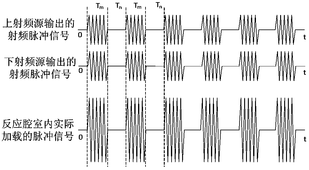
[0041] This embodiment provides a plasma generation method, comprising: the upper radio frequency source outputs a main pulse signal for exciting the process gas in the reaction chamber to form plasma, and during the closing phase of the main pulse signal, the upper radio frequency source outputs one or more Auxiliary pulse signal, the auxiliary pulse signal can maintain the plasma in the reaction chamber in an ignition state during the off stage of the main pulse signal.

[0042] During the closing phase of the main pulse signal, the upper radio frequency source outputs one or more auxiliary pulse signals, and the plasma in the reaction chamber is kept in a glowing state during the closing phase of the main pulse signal through the auxiliary pulse signal, which can prevent the reaction chamber from being Plasma extinction in the off-phase of the main pulse signal caused by insufficient main pulse power loaded, thereby achieving stable generation of plasma in the reaction chamb...

Embodiment 2

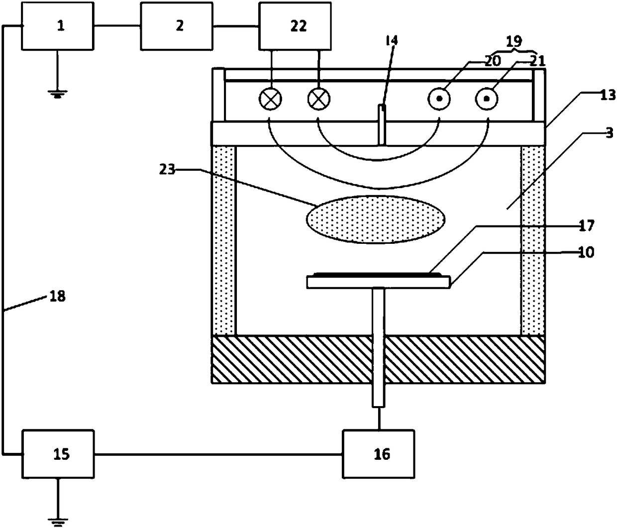
[0056] Based on the plasma generation method in Embodiment 1, this embodiment provides a plasma generation device, such as Figure 7 As shown, including the upper radio frequency source 1, the upper radio frequency source 1 can output a main pulse signal to excite the process gas in the reaction chamber 3 to form a plasma 23, and the upper radio frequency source 1 can also output one or A plurality of auxiliary pulse signals, the auxiliary pulse signals can maintain the plasma 23 in the reaction chamber 3 in an ignition state during the off phase of the main pulse signal.

[0057]In this embodiment, the upper radio frequency source 1 includes a main radio frequency source 11, the main radio frequency source 11 is connected to the main coil 4 at the top of the reaction chamber 3 through the first matcher 2, the main radio frequency source 11 can output the main pulse signal, and the upper radio frequency source 1 Also comprise auxiliary radio frequency source 12, auxiliary radi...

Embodiment 3

[0069] Based on the plasma generation method provided in Embodiment 1, this embodiment provides a plasma generation device, the difference from Embodiment 2 is that, as Figure 9 As shown, the upper radio frequency source 1 only includes the main radio frequency source 11, that is, the plasma generating device in this embodiment is only provided with the main radio frequency source 11, and no auxiliary radio frequency source is provided. The main radio frequency source 11 can output a main pulse signal, and output one or more auxiliary pulse signals during the off phase of the main pulse signal.

[0070] Correspondingly, the plasma generating device also includes a first control switch 8, the first control switch 8 is connected between the output end of the main radio frequency source 11 and the input end of the first matcher 2; the first control switch 8 is turned on or off , to control the main radio frequency source 11 to output or stop outputting the main pulse signal or t...


PUM


Abstract

The invention provides a plasma generation method and device, and semiconductor processing equipment. The plasma generation method comprises the following steps that an upper radio frequency source outputs a main pulse signal so as to motivate a technology gas in a reaction chamber to form a plasma; and in the closing phase of the main pulse signal, the upper radio frequency source outputs one ormore auxiliary pulse signals, and the auxiliary pulse signals can maintain the plasma in the reaction chamber to be in a starting state during the closing phase of the main pulse signal. By using theplasma generation method, the auxiliary pulse signals are used to maintain the plasma in the reaction chamber to be in the starting state during the closing phase of the main pulse signal, and the plasma in the reaction chamber can be prevented from being quenched during the closing phase of the main pulse signal due to insufficient loaded main pulse power so that the stable generation of the plasma in the reaction chamber and the enlargement of a technology window are realized, and a plasma technology can be performed stably.

Description

technical field [0001] The invention relates to the technical field of magnetron sputtering, in particular to a plasma generation method and device and semiconductor processing equipment. Background technique [0002] In semiconductor equipment, the plasma equipment used for silicon etching process usually adopts the principle of inductively coupled plasma (ICP), and the radio frequency energy is provided by the radio frequency power supply to ionize the special gas (such as argon Ar, helium, etc.) in the high vacuum state in the chamber. Gas He, Nitrogen N 2 , hydrogen H 2 etc.), generate a plasma containing a large number of active particles such as electrons, ions, excited atoms, molecules and free radicals, and complex interactions between these active particles and the wafer placed in the cavity and exposed to the plasma environment The interaction causes various physical and chemical reactions to occur on the surface of the wafer material, thereby changing the surfac...

Claims


Application Information

Patent Timeline
Patent Type & Authority Applications(China)
IPC IPC(8): H05H1/24H01J37/34
CPCH01J37/3405H01J37/3467H05H1/24
Inventor 成晓阳韦刚卫晶柏锦枝杨京
Owner BEIJING NAURA MICROELECTRONICS EQUIP CO LTD
Why Eureka
Eureka Blog
Learn More