METHOD FOR CLEANING SiC MONOCRYSTAL GROWTH FURNACE

A cleaning method and growth furnace technology, applied in the direction of single crystal growth, single crystal growth, crystal growth, etc., can solve the problems of yield deterioration, long operation time, productivity impact, etc., and achieve the effect of inhibiting damage

Active Publication Date: 2018-09-14
SHOWA DENKO KK
View PDF7 Cites 1 Cited by
  • Summary
  • Abstract
  • Description
  • Claims
  • Application Information

AI Technical Summary

Problems solved by technology

[0009] Removal of deposited silicon carbide and replacement of the growth furnace require extremely long operating hours, and the re

Method used


Image

  • METHOD FOR CLEANING SiC MONOCRYSTAL GROWTH FURNACE
  • METHOD FOR CLEANING SiC MONOCRYSTAL GROWTH FURNACE
  • METHOD FOR CLEANING SiC MONOCRYSTAL GROWTH FURNACE

Examples


Embodiment 1

[0065]In a SiC single crystal growth furnace having a furnace base material in which SiC is coated on a carbon base material, a 1 cm square portion without deposits was cut out and used as a control sample. The SiC epitaxial growth process was repeated in this furnace, and the base material in the furnace on which the SiC deposit was deposited was cut out in a size of 5 mm square, and used as a sample for evaluation.

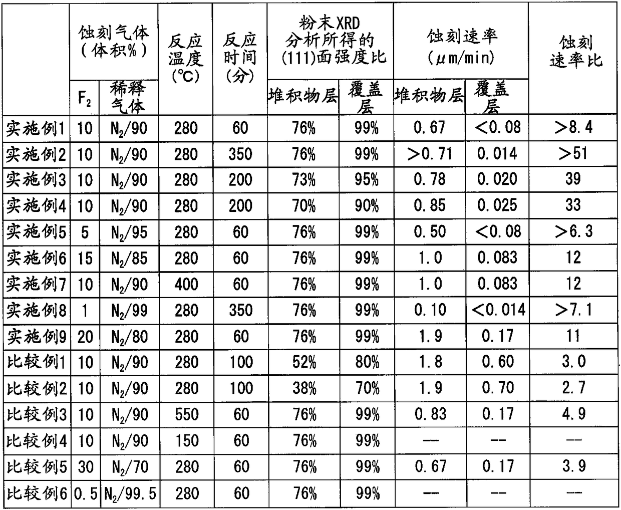
[0066] These two samples were resolved by powder XRD analysis. The normal SiC coating film of the control sample is polycrystalline 3C-SiC, and the intensity ratio of the (111) plane is 99%. On the other hand, the deposit plane of the sample for evaluation was also a 3C-SiC polycrystal, but the intensity ratio of the (111) plane was 76%. As crystal orientation planes other than the (111) plane, (200) plane, (220) plane, and (311) plane were observed.

[0067] The X'pert Pro MPD manufactured by PANalytical was used as the powder XRD analysis device. Regarding t...

Embodiment 2

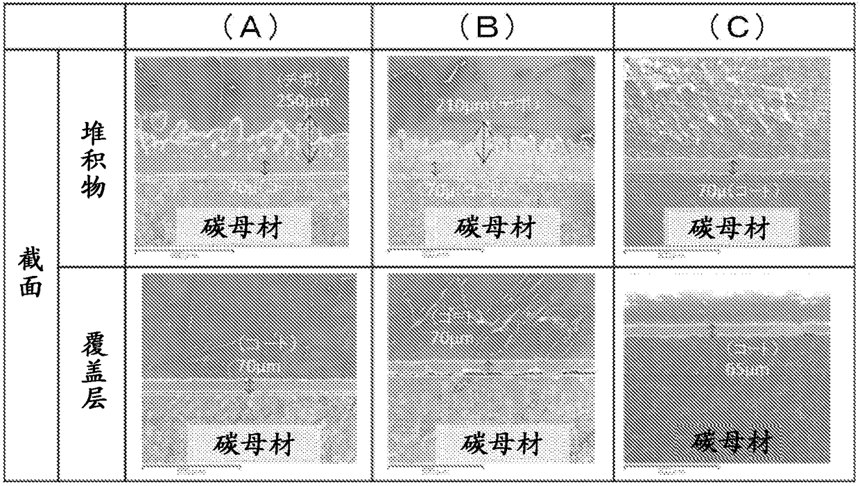
[0073] A cleaning test was performed under the same conditions as in Example 1 except that the flow time of the cleaning gas was set to 350 minutes. As a result, such as figure 2 As shown in (C), the SiC deposit layer disappeared, but the thickness of the SiC coating film was 65 μm.

[0074] The etching rate for the SiC deposit layer was 0.71 μm / min or higher, and the etching rate for the SiC cover film was 0.014 μ / min, and the etching rate ratio of the SiC deposit layer to the SiC cover film was 51 or higher.

Embodiment 3

[0076] As the SiC coating used for the base material in the furnace, a SiC coating having different crystal orientation plane strengths, that is, a SiC coating having an intensity ratio of the (111) plane obtained by powder XRD analysis of 95% was used. The intensity ratio of the crystal orientation plane (111) plane of the SiC deposit layer at this time was 73%.

[0077] A cleaning test was performed under the same conditions as in Example 1 except that the gas flow time was set to 200 minutes. In addition, as a result of SEM observation of the cross-section, the thickness of the SiC coating film was 70 μm, and the thickness of the SiC deposit (depo) of the evaluation sample was about 250 μm, which was the same as in Example 1.

[0078] As a result, the SiC deposit layer was reduced to 95 μm, and the SiC coating film was reduced to 66 μm.

[0079] The etching rate was 0.78 μm / min for the SiC deposit layer and 0.020 μm / min for the SiC cover film, and the etching rate ratio of...


PUM

PropertyMeasurementUnit
Thicknessaaaaaaaaaa
Thicknessaaaaaaaaaa
Etch rateaaaaaaaaaa

Abstract

In the present method for cleaning an SiC monocrystal growth furnace, gas is used to clean an SiC monocrystal growth furnace provided with an in-chamber substrate comprising 3C-SiC polycrystals, in which the strength ratio of at least the (111) plane with respect to the other crystal planes is, according to powder XRD analysis, 85% to 100%. Said method involves causing a mixed gas, comprising fluorine gas as well as an inert gas and/or air, to flow, in a non-plasma state, through the interior of the SiC monocrystal growth furnace, thereby selectively removing SiC deposits deposited inside of the SiC monocrystal growth furnace. The mixed gas comprises 1 vol% to 20 vol% fluorine gas and 80 vol% to 99 vol% inert gas, and the internal temperature of the SiC monocrystal growth furnace is 200 DEG C to 500 DEG C.

Description

technical field [0001] The invention relates to a cleaning method for a SiC single crystal growth furnace. [0002] This application claims priority based on Patent Application No. 2015-256287 filed in Japan on December 28, 2015, the content of which is incorporated herein by reference. Background technique [0003] Silicon carbide (SiC) is used in many ways as an important ceramic material. In recent years, the epitaxial growth technology of silicon carbide has attracted attention, especially from the perspective of high insulation breakdown voltage and reliability at high temperature operation, low power consumption transistors and other applications have been developed. [0004] As silicon carbide used for such applications, a high-purity single crystal bulk or film (both thin and thick films are included) is required. [0005] As a method of forming a silicon carbide single crystal film, it is known to use a chemical vapor deposition method (Chemical Vapor Deposition m...

Claims


Application Information

Patent Timeline
IPC IPC(8): C30B29/36C23C14/00C23C16/44
CPCC30B29/36C23C14/564C30B23/00C23C16/4405C23C14/022C23C16/0245B08B5/00B08B9/00C30B25/02
Inventor 谷本阳祐栗原秀行
Owner SHOWA DENKO KK
Why Eureka
Try Eureka