Hydrogen fueled two-stroke engine and power system thereof

A power system and engine technology, applied in combustion engines, internal combustion piston engines, fuel systems, etc., can solve the problems of high price, inability to promote, and consume other resources, and achieve the effect of improving utilization.

Active Publication Date: 2018-09-18
SHANGHAI KELAIPU ENERGY TECH CO LTD
View PDF6 Cites 2 Cited by
  • Summary
  • Abstract
  • Description
  • Claims
  • Application Information

AI Technical Summary

Problems solved by technology

The promotion of hydrogen energy power needs to solve three technical problems: one is to produce a large amount of cheap hydrogen, the traditional electrolysis method is expensive and co

Method used


Image

  • Hydrogen fueled two-stroke engine and power system thereof
  • Hydrogen fueled two-stroke engine and power system thereof
  • Hydrogen fueled two-stroke engine and power system thereof

Examples


Embodiment 1

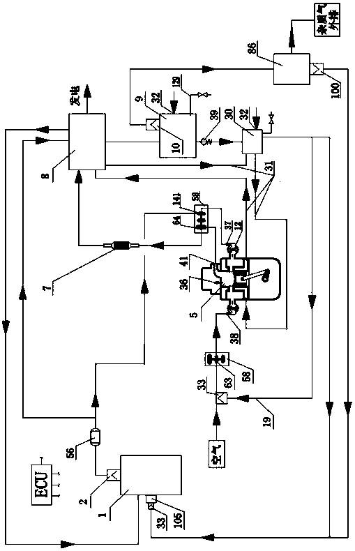
[0026] A power system of a hydrogen-burning two-stroke diesel engine of the present invention such as figure 1 As shown, it includes an ECU, a hydrogen fuel engine, a metal hydride storage tank 1, a three-way catalytic converter 7, a turbocharger unit 58, an exhaust waste heat utilization unit 8, a hydrogen purification unit 86, a cooling water tank 30, a gas-liquid separator 9 and Low pressure hydrogen buffer tank 56.

[0027] Such as Figure 7As shown in the metal hydride storage tank 1, the metal hydride storage tank is equipped with a metal hydride that reacts with water to release hydrogen, which is magnesium hydride in this embodiment. The metal hydride storage tank 1 is composed of a tank body 135 and an insulation layer 137 outside the tank body, and a water spray pipeline 134 is arranged inside the tank body. The bottom of the tank body is provided with a pressure sensor 71 , an explosion-proof valve 72 , a hydrogen outlet 73 , a moisture inlet and a temperature sen...

Embodiment 2

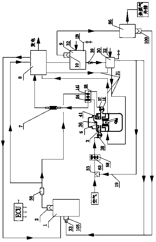
[0035] Another embodiment of the present invention is as figure 2 As shown, it includes an ECU, a hydrogen fuel engine, a metal hydride storage tank 1, a three-way catalytic converter 7, a turbocharger unit 58, an exhaust waste heat utilization unit 8, a hydrogen purification unit 86, a cooling water tank 30, a gas-liquid separator 9 and Low pressure hydrogen buffer tank 56.

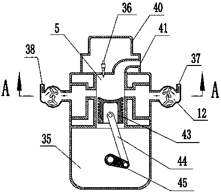
[0036] The difference between Embodiment 2 and Embodiment 1 lies in the structure of the hydrogen fuel engine. Such as figure 2 , Figure 5 with Image 6 As shown, the hydrogen inlet 37 and the air inlet 38 are independently arranged and separated from each other up and down, and the hydrogen inlet chamber and the air inlet chamber are divided into two annular cavities that are independent of each other up and down through the annular partition baffle 3 along the radial direction. The upper cavity is an air intake chamber, and the lower cavity is a hydrogen intake chamber. The hydrogen inlet 37 is...


PUM


Abstract

The invention relates to a hydrogen fueled two-stroke engine and a power system thereof. The hydrogen fuel engine is provided with an air cylinder, a cylinder cover and a crank case, wherein a spark plug and an exhaust hole are arranged on the cylinder cover; a piston is arranged in the air cylinder; a crank shaft is arranged in the crank case; the piston is connected with the crank shaft througha connecting rod; a hydrogen inlet and an air inlet are formed in a wall of the air cylinder; the hydrogen inlet is connected with a hydrogen inlet chamber through a gas compression unit; the air inlet is connected with an air inlet chamber through the other gas injection unit; and the hydrogen inlet chamber and the air inlet chamber are independently arranged in a separating way and communicate with the air cylinder. According to the two-stroke engine, the hydrogen concentrated-combustion operation emission meets the cleaning standard, and the backfire problem of a hydrogen internal combustion engine is solved by feeding hydrogen and air in a separating way. An exhaust afterheat utilization unit recycles exhaust afterheat and engine cooling water afterheat for generating power, so that the utilization rate of a hydrogen fuel and the power per liter of the engine are improved; and metal hydride in a metal hydride storage tank is stored at ordinary pressure, the hydrogen is desorbed through hydration, and the weight hydrogen storage rate reaches 15 percent or above.

Description

technical field [0001] The invention belongs to the technical field of new energy engines, and relates to a hydrogen-burning two-stroke engine and a power system thereof. Background technique [0002] Energy shortage, environmental pollution, and global climate change make it urgent to develop clean, efficient, safe and sustainable energy, among which hydrogen energy is being valued by more and more countries. In the 21st century, the engine industry has developed rapidly, but gasoline engines and diesel engines are still the main types of vehicle engines. Both gasoline and diesel are non-renewable resources. In order to alleviate a series of negative effects brought about by the scarcity of petroleum resources and reduce air pollution and engine exhaust emissions, it is necessary to find alternative fuels for engines, and hydrogen energy is currently the most ideal clean fuel. With the increasingly stringent environmental protection measures around the world, hydrogen ener...

Claims


Application Information

Patent Timeline
IPC IPC(8): F02B43/10F02B75/02F02M21/02F02G5/04F02F1/22
CPCF02B43/10F02B75/02F02B2075/025F02F1/22F02G5/04F02M21/0206F02M21/0221F02M21/0227F02M21/0284Y02T10/12Y02T10/30
Inventor 贾鹏
Owner SHANGHAI KELAIPU ENERGY TECH CO LTD
Why Eureka
Try Eureka