Lithium niobate doped silica fiber

A quartz fiber, lithium niobate technology, applied in cladding fiber, multi-layer core/cladding fiber, light guide, etc. Mature preparation process, high Raman gain effect

Inactive Publication Date: 2018-09-28
SHANGHAI UNIV
View PDF10 Cites 6 Cited by
  • Summary
  • Abstract
  • Description
  • Claims
  • Application Information

AI Technical Summary

Problems solved by technology

Although silicate and other glass optical fibers have high Raman gain coefficients, they have huge losses, and at the same time, they cannot be well fused with the quartz optical fibers commonly used in existing optical communication systems, so they cannot be practically applied.
However, hafnium-doped silica fiber, niobium-doped silica fiber, and niobium chloride-doped silica fiber can be well connected to existing optical communication systems, but the loss of the fiber itself is high, resulting in Raman gain being offset by loss, which cannot be achieved very well. well amplified signal light

Method used


Image

  • Lithium niobate doped silica fiber
  • Lithium niobate doped silica fiber
  • Lithium niobate doped silica fiber

Examples


Embodiment 1

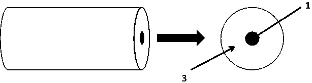
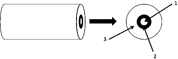
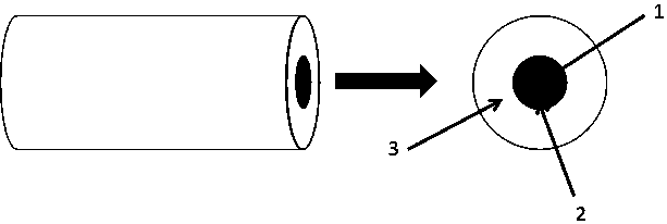
[0017] see Figure 1~Figure 3 , the lithium niobate-doped silica fiber is made by adding lithium niobate high-temperature gasification deposition process in the improved chemical vapor deposition (MCVD) preparation process, and the prepared lithium niobate-doped silica fiber has a core layer 1 Doped lithium niobate matching structure, inner cladding layer 2 doped lithium niobate structure, core layer 1 and inner cladding layer 2 co-doped lithium niobate structure.

Embodiment 2

[0019] This embodiment is basically the same as Embodiment 1, and the special features are as follows:

[0020] The lithium niobate-doped silica optical fiber structure is a matching structure in which lithium niobate is doped only in the core, or an inner cladding doped structure in which lithium niobate is doped only in the inner cladding, or an inner cladding doped structure in which lithium niobate is doped only in the core and the inner cladding The layer is doped with lithium niobate at the same time, the refractive index difference is not less than 1.5%, the loss is less than 5dB / km, and the Raman gain coefficient is more than 2 times higher than that of ordinary single-mode fiber.

Embodiment 3

[0022] This embodiment specifically describes the preparation process of the lithium niobate-doped silica optical fiber preform, combining Figure 4 as shown, Figure 4 It is a schematic diagram of the preparation process of lithium niobate doped silica optical fiber preform. The whole process device includes input oxygen 4 , liquid silicon tetrachloride 5 , liquid germanium tetrachloride 6 , lithium niobate crystal 7 , graphite furnace 8 , pure quartz glass substrate tube 9 , oxyhydrogen flame 10 and tail gas treatment device 11 .

[0023] After the above materials are prepared and the preparation device is set up, the oxyhydrogen flame 10 is turned on and the mobile switch of the oxyhydrogen flame device is turned on at the same time. The oxyhydrogen flame 10 can move back and forth under the quartz glass substrate tube 9 to heat the substrate tube 9 at a high temperature, so that the mixed gas flowing into the substrate tube 9 produces a chemical reaction at high temperatu...


PUM


Abstract

The invention relates to a lithium niobate doped silica fiber. The fiber is prepared by adding the high-temperature gasification lithium niobate process to the improved chemical gas-phase deposition process. The prepared lithium niobate doped silica fiber is of a fiber core layer lithium niobate doped matched type structure or an inner wrapping layer lithium niobate doped structure or a fiber coreand inner wrapping layer lithium niobate doped structure, and the lithium niobate doped silica fibers of the three structures all have high refractive index difference, low loss and high Raman gain coefficient. The fiber is used for a Raman fiber amplifier, can obtain high Raman gains, and can overcome the defect that a traditional single-mode optical fiber Raman amplifier is low in gain. Meanwhile, the preparing process is mature, and the batched production of the lithium niobate doped silica fiber can be realized.

Description

technical field [0001] The invention relates to a lithium niobate doped quartz optical fiber, which belongs to the field of optical fiber communication and optical fiber sensing. Background technique [0002] With the advent of the era of high-speed, large-bandwidth, and low-loss all-fiber communication, research on fiber amplifiers used in all-optical relays has become a top priority. The traditional erbium-doped fiber amplifier (EDFA) has the advantages of high gain, high output power, low noise, and polarization-independent, and has good amplification characteristics in the current communication band. [0003] However, with the development of wavelength division multiplexing system research towards larger capacity and longer transmission distance, EDFA has gradually become the "bottleneck" for further improvement of system capacity distance product. First of all, EDFA is limited by erbium ions, providing a gain bandwidth of about 70nm, which only accounts for a small par...

Claims


Application Information

Patent Timeline
Patent Type & Authority Applications(China)
IPC IPC(8): G02B6/02G02B6/036
CPCG02B6/02G02B6/036G02B6/03622
Inventor 王廷云陈振宜陈娜庞拂飞文建湘刘书朋
Owner SHANGHAI UNIV
Why Eureka
Try Eureka