Ultra-short pulse Raman optical fiber amplifier
A technology of ultra-short pulse and Raman fiber, which is applied in the direction of lasers, laser components, phonon exciters, etc., can solve the problems of insufficient practicability, laser output noise, and high system complexity, and achieve high Raman gain and good coherence effect
- Summary
- Abstract
- Description
- Claims
- Application Information
AI Technical Summary
Problems solved by technology
Method used
Image
Examples
Embodiment 1
[0022] Example 1, see figure 1 .
[0023] figure 1 It is a schematic block diagram of the structure of the ultrashort pulse Raman fiber amplifier. Pulse laser pump source 1, continuous optical signal source 2, pump / signal laser beam combining device 3, Raman gain fiber 4, pump / signal beam splitting device 5 through the fiber fusion splicer such as figure 1 Welded together. The center wavelength of the pulsed laser pumping source 1 is 1117nm, and the pulse width is <100ps. The central wavelength of the continuous optical signal source 2 is 1310 nm. The pump / signal laser beam combiner 3 is a 1117nm / 1310nm wavelength division multiplexer. The Raman gain fiber 4 is a phosphorus-doped silica fiber, and the Raman gain is 1.2 / (W·km). The pump / signal laser beam splitter 5 is a 1117nm / 1310nm wavelength division multiplexer.
Embodiment 2
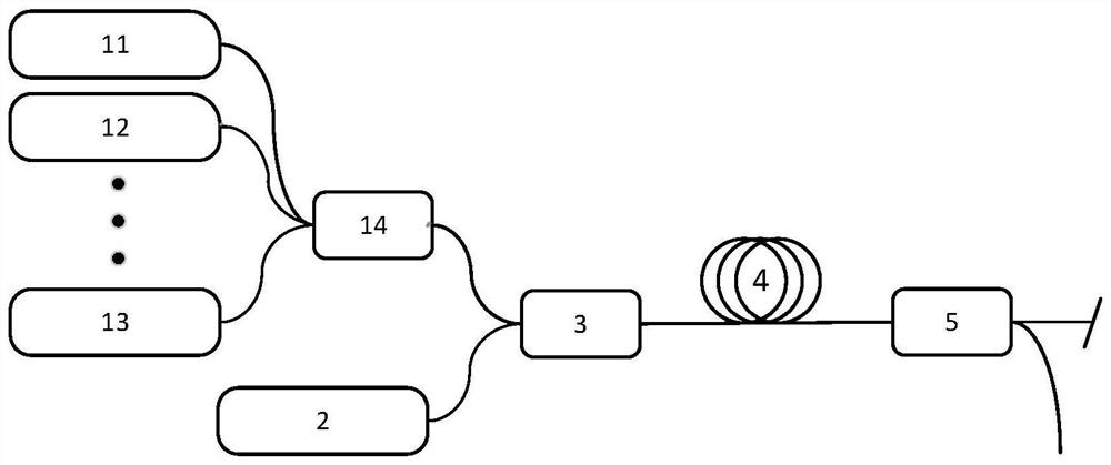
[0024] Example 2, see figure 2 .
[0025] figure 2 Schematic block diagram of the multi-wavelength pumping structure for the ultrashort pulse Raman fiber amplifier. The central wavelengths of the pulsed laser pumping source 11, the pulsed laser pumping source 12, and the pulsed laser pumping source 13 are 1064nm, 1067nm, and 1070nm respectively, and the pulse width is <100ps. The laser combining device 14 is a wavelength division multiplexer. The continuous optical signal source 2 has a central wavelength of 1120nm and a line width of <10nm. The pump / signal laser beam combiner 3 is a wavelength division multiplexer. The Raman gain fiber 4 is a polarization-maintaining silica fiber, and the Raman gain is 1.8 / (W·km). The pumping / signal laser beam splitting device 5 is a 1067nm / 1120nm wavelength division multiplexer.
Embodiment 3
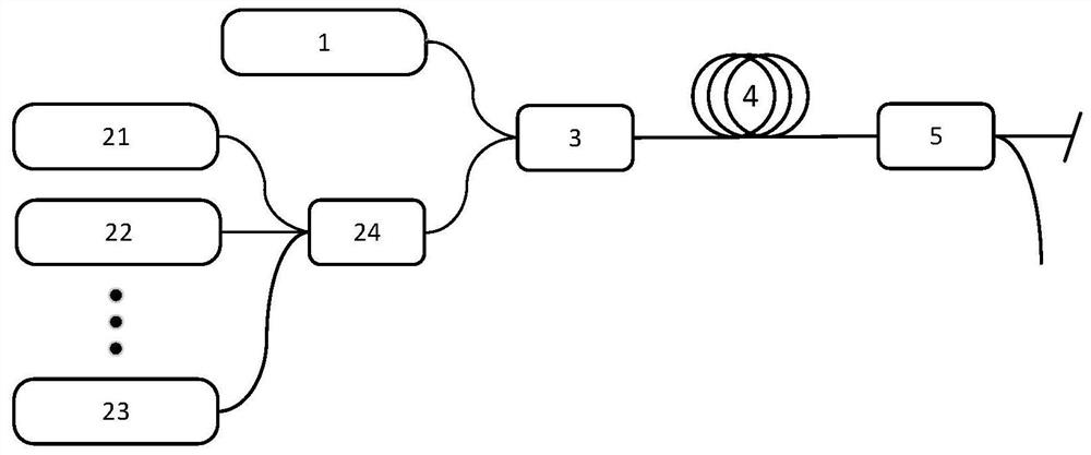
[0026] Example 3, see image 3 .
[0027] image 3 It is a schematic block diagram of the multi-signal injection structure of the ultrashort pulse Raman fiber amplifier. The center wavelength of the pulsed laser pumping source 1 is 1064nm, and the pulse width is <100ps. The central wavelengths of the continuous optical signal source 21 , the continuous optical signal source 22 , and the continuous optical signal source 23 are 1120 nm, 1178 nm, and 1238 nm, respectively, and the line width is <1 nm. The laser beam combiner 24 is a wavelength division multiplexer. The pump / signal laser beam combiner 3 is a wavelength division multiplexer. The Raman gain fiber 4 is a polarization-maintaining silica fiber, and the Raman gain is 2.5 / (W·km). The pump / signal laser beam splitter 5 is a wavelength division multiplexer. Under the excitation of the pulsed laser pump source 1, the continuous optical signal source 21, the continuous optical signal source 22 and the continuous optical...
PUM
| Property | Measurement | Unit |
|---|---|---|
| wavelength | aaaaa | aaaaa |
Abstract
Description
Claims
Application Information
 - R&D
- Intellectual Property
- Life Sciences
- Materials
- Tech Scout
- Unparalleled Data Quality
- Higher Quality Content
- 60% Fewer Hallucinations
Browse by: Latest US Patents, China's latest patents, Technical Efficacy Thesaurus, Application Domain, Technology Topic, Popular Technical Reports.
© 2025 PatSnap. All rights reserved.Legal|Privacy policy|Modern Slavery Act Transparency Statement|Sitemap|About US| Contact US: help@patsnap.com


