
Tunnel kiln superposition sintering system for foamed ceramic light plates

A technology for foaming ceramics and tunnel kiln, applied in the field of ceramic plates, can solve the problems of poor overall product uniformity, difficult oxidation of the formulation system, long foaming time, etc., to reduce manual labor, reduce oxidation reaction stage time, improve Yield effect

Inactive Publication Date: 2018-10-16
KEDA INDUSTRIAL GROUP CO LTD
View PDF2 Cites 0 Cited by
  • Summary
  • Abstract
  • Description
  • Claims
  • Application Information

AI Technical Summary

Problems solved by technology

Because the existing foamed bricks are relatively thick and the formula system is difficult to oxidize, the formula system of the foamed ceramics determines that it must be fired in a tunnel kiln. The firing cycle of the tunnel kiln is generally 24-26 hours, and the firing cycle is long. , higher temperature
[0005] And, if figure 1 As shown, the foamed ceramic plate made by the prior art has multi-layer pores formed inside
During the foaming process, due to the long foaming time and the influence of gravity, the pores in the lower layer will be flattened, making the overall uniformity of the product poor
[0006] In addition, the existing tunnel kiln firing is single-layer stack firing, basically manual operation, requiring a lot of manpower, low efficiency and high cost

Method used


Image

  • Tunnel kiln superposition sintering system for foamed ceramic light plates
  • Tunnel kiln superposition sintering system for foamed ceramic light plates
  • Tunnel kiln superposition sintering system for foamed ceramic light plates

Examples


Embodiment 1

[0110] (1) Formula: tile polishing waste 95.5%, foaming agent 0.5%, manganese dioxide stabilizer 4%.

[0111] (2) Preparation method:

[0112] The raw materials are mixed according to the proportion, and the powder is obtained through ball milling;

[0113] The powder is distributed on the kiln car through the feeding line, and then the kiln car is pushed into the tunnel kiln for three-layer stacking firing treatment to obtain foamed ceramic light boards. The firing method is as follows: (a) heating to 800°C , and kept at 800°C for 20min, wherein, the heating rate from 0°C to 400°C was 10°C / min, and the heating rate from 400°C to 800°C was 3°C / min; (b) heating to 1150°C, And keep it at the highest temperature for 40min, wherein, the heating rate from 800°C to 1150°C is 3°C / min; (c) slowly cool down, the cooling rate from 1150°C to 600°C is 3°C / min, The cooling rate for cooling down to 50°C is 1°C / min;

[0114] Finally, the foamed ceramic light board is unloaded through the ...

Embodiment 2

[0116] (1) Formula: tile polishing waste 90%, clay 1%, feldspar 8.8%, foaming agent 0.1%, stabilizer 0.1%.

[0117] (2) Preparation method:

[0118] The raw materials are mixed according to the proportion, and the powder is obtained through ball milling;

[0119] The powder is distributed on the kiln car through the feeding line, and then the kiln car is pushed into the tunnel kiln for three-layer stacking firing treatment to obtain foamed ceramic light boards. The firing method is as follows: (a) heating to 820 °C , and kept at 820°C for 15 minutes, wherein, the heating rate from 0°C to 400°C was 15°C / min, and the heating rate from 400°C to 820°C was 5°C / min; (b) heating to 1170°C, And keep it at the highest temperature for 30min, wherein, the heating rate from 820°C to 1170°C is 4°C / min; (c) slow down the temperature, the cooling rate from 1170°C to 600°C is 4°C / min, The cooling rate for cooling down to 50°C is 2°C / min;

[0120] Finally, the foamed ceramic light board is ...

Embodiment 3

[0122] (1) Formula: tile polishing waste 92%, clay 5%, feldspar 2%, foaming agent 0.2%, stabilizer 0.8%.

[0123] (2) Preparation method:

[0124] The raw materials are mixed according to the proportion, and the powder is obtained through ball milling;

[0125] The powder is distributed on the kiln car through the feeding line, and then the kiln car is pushed into the tunnel kiln for three-layer stacking firing treatment to obtain foamed ceramic light boards. The firing method is as follows: (a) heating to 830°C , and kept at 830°C for 25min, wherein, the heating rate from 0°C to 400°C was 15°C / min, and the heating rate from 400°C to 830°C was 5°C / min; (b) heating to 1180°C, And keep warm at the highest temperature for 0-60min, wherein, the heating rate from 830°C to 1180°C is 5°C / min; (c) slow down the temperature, the cooling rate from 1180°C to 600°C is 5°C / min, by The cooling rate from 600°C to 50°C is 2°C / min;

[0126] Finally, the foamed ceramic light board is unloade...


PUM

PropertyMeasurementUnit
compressive strengthaaaaaaaaaa
densityaaaaaaaaaa
water absorptionaaaaaaaaaa

Abstract

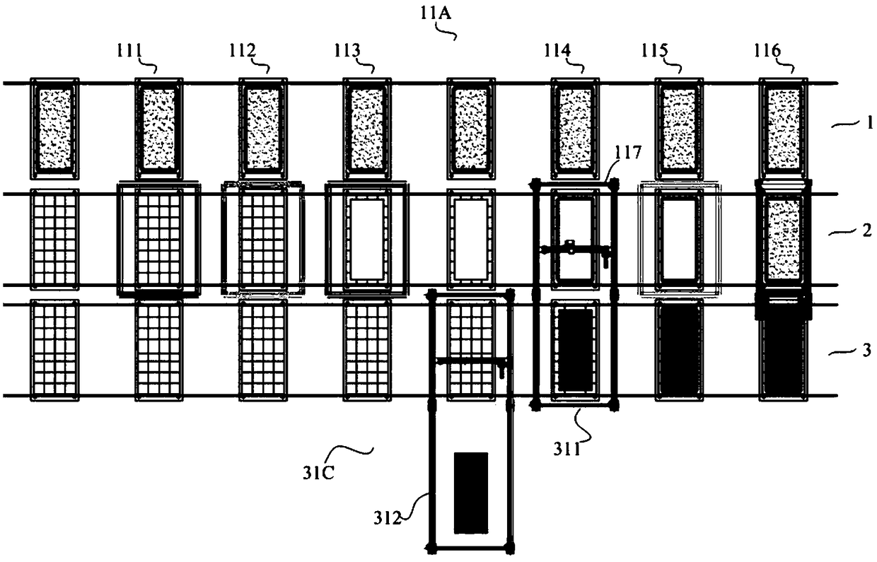
The invention discloses a tunnel kiln superposition sintering system for foamed ceramic light plates. A feeding line, a tunnel kiln and a discharging line are included, wherein a kiln trolley comprises a support which is provided with at least two layers of saggers; each layer of sagger comprises a cushion plate, encircling plates and high temperature resistant paper; the corresponding encirclingplates are erected around each cushion plate; the cushion plates and the encircling plates are each provided with the corresponding high temperature resistant paper; the feeding line comprises at least two feeding units; and each feeding unit comprises a cleaning unit used for cleaning the corresponding cushion plate and the corresponding encircling plates, a cushion plate sorting unit used for sorting or erecting the corresponding cushion plate, a first laying unit used for laying the corresponding high temperature resistant paper on the corresponding cushion plate, an encircling plate erecting unit used for erecting the corresponding encircling plates on the corresponding cushion plate, a second laying unit used for laying the corresponding high temperature resistant paper on the corresponding encircling plates, and a material distributing unit performing material distribution in the corresponding sagger. By adopting the tunnel kiln superposition sintering system for the foamed ceramic light plates, multi-layer superposition sintering is achieved, the automation degree is high, the production efficiency is high, and cost and space are saved.

Description

technical field [0001] The invention relates to the technical field of ceramic plates, in particular to a tunnel kiln stack firing system for foamed ceramic light plates. Background technique [0002] The matrix materials used in foamed ceramics come from wastes such as ceramic factory waste and industrial waste (tile polishing waste or cinder or stone waste, etc.). If these wastes are not treated, they will be piled up or landfilled randomly. Waste of resources. [0003] This foamed ceramic product has gradually begun to be used nationwide due to its advantages of light weight, high strength, fire prevention, earthquake resistance, heat insulation, sound insulation, strong combination, easy handling, and wide application. And because the raw materials are solid wastes such as coal slag, tile polishing waste, slag, etc., it has positive social significance in terms of full utilization of resources and environmental protection. [0004] The formula system of the existing fo...

Claims


Application Information

Patent Timeline
Patent Type & Authority Applications(China)
IPC IPC(8): F27B9/26F27B9/38F27B9/39F27B9/30F27D5/00C04B33/132C04B33/13C04B38/02
CPCC04B33/13C04B33/1324C04B38/02C04B2235/3472C04B2235/3481C04B2235/77C04B2235/96C04B2235/9607F27B9/262F27B9/30F27B9/38F27B9/39F27B2009/305F27B2009/382F27B2009/384F27D5/0031F27M2001/035Y02P40/60
Inventor 林智
Owner KEDA INDUSTRIAL GROUP CO LTD
Learn More