Composite grid IGBT chip with three-dimensional channel

A compound gate and chip technology, applied in electrical components, circuits, semiconductor devices, etc., to achieve high current density, reduced output capacitance, and small parasitic capacitance

Active Publication Date: 2018-10-19
ZHUZHOU CRRC TIMES SEMICON CO LTD
View PDF7 Cites 6 Cited by
  • Summary
  • Abstract
  • Description
  • Claims
  • Application Information

AI Technical Summary

Problems solved by technology

[0006] figure 2 and image 3 The bottom of the trench gate has a certain limit on the resistance capacity of the IGBT chip
its with figure 1 Compared with the IGBT chip with a pl

Method used


Image

  • Composite grid IGBT chip with three-dimensional channel
  • Composite grid IGBT chip with three-dimensional channel
  • Composite grid IGBT chip with three-dimensional channel

Examples


no. 1 example

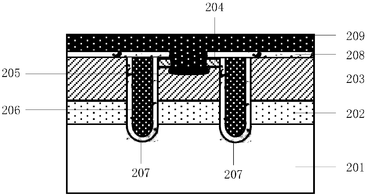
[0041] The composite gate IGBT chip of this embodiment includes a plurality of cells. In order to more clearly illustrate the composite gate IGBT chip of this embodiment, the following uses Figure 4 The schematic diagram of the structure of a single bar-shaped cell is shown as an example for detailed explanation.

[0042] Figure 4 It is a schematic structural diagram of a composite gate IGBT chip with a three-dimensional channel in the first embodiment of the present invention. Such as Figure 4As shown, it includes a substrate 1 , cells disposed on the substrate 1 , and an N-type buffer layer 2 , a P-type layer 3 and an anode metal layer 4 disposed below the substrate 1 . Among them, the cell mainly includes: a trench polysilicon gate electrode 5, a first oxide layer 6, two P well regions 7, two doped regions (the doped regions include N++ doped regions 8 and P++ doped regions 9), Two second oxide layers 10 , two planar polysilicon gate electrodes 11 , two third oxide l...

no. 2 example

[0058] This embodiment is a further optimization of the first embodiment.

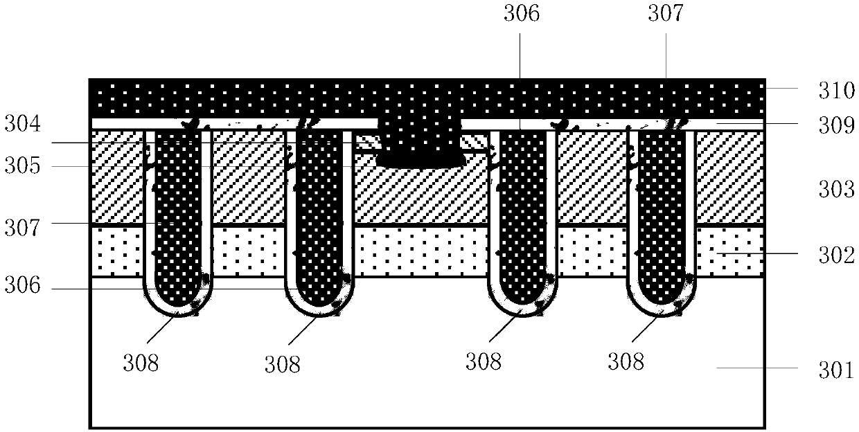
[0059] Figure 5 It is a schematic structural diagram of a composite gate IGBT chip with a three-dimensional channel in the second embodiment of the present invention. Such as Figure 5 shown in Figure 4 An N well region 15 is added to the shown cell. The N well region 15 is located below the P well region 7 and is in contact with the lower surface and the side of the P well region 7 , and the width of the N well region 15 is greater than that of the P well region 7 .

[0060] In this embodiment, an N well region is added around the P well region to further increase the conductance modulation effect of the IGBT chip in the drift region.


PUM


Abstract

The invention discloses a composite grid IGBT chip with a three-dimensional channel. The chip includes multiple cells. Each of the cells includes: a trench polysilicon gate electrode located in an intermediate area of the cell; a first oxide layer surrounding the trench polysilicon gate electrode; P well areas formed by injecting P type impurities into the cell on both side areas of a trench; doping areas formed by injecting impurities into the P well areas on both sides of the trench, wherein the width of the doping areas is smaller than the width of the P well areas, and the doping areas include an N++ doping area and a P++ doping area; second oxide layers are located on two side areas, being on the cell, of the doping areas, wherein the second oxide layers are used for covering the surface of the two side areas of the two P well areas, the surface of the P well areas without the doping areas, and partial doping areas; planar polysilicon gate electrodes formed on the second oxide layers; and third oxide layers covering the planar polysilicon gate electrodes. The chip can enable the electric current density of the IGBT chip to be improved, so as to reduce a conducting voltage drop.

Description

technical field [0001] The invention relates to the technical field of semiconductor devices, in particular to a composite gate IGBT chip with a three-dimensional channel. Background technique [0002] Since the advent of IGBT (Insulated Gate Bipolar Transistor, Insulated Gate Bipolar Transistor) devices around 1980, due to the characteristics of bipolar transistor on-state voltage drop and high current density, and MOSFET (Metal-Oxide-Semiconductor Field -Effect Transistor, Metal-Oxide Semiconductor Field Effect Transistor) has high input impedance and fast response, and is widely used in rail transit, smart grid, industrial frequency conversion and new energy development and other fields. [0003] figure 1 It is a schematic cross-sectional view of a half cell of an IGBT chip with a planar gate structure in the prior art. Such as figure 1 As shown, it mainly includes: substrate 101, N well region 102, P well region 103, N+ doped region 104, P+ doped region 105, planar ga...

Claims


Application Information

Patent Timeline
IPC IPC(8): H01L29/739H01L29/06H01L29/423
CPCH01L29/0684H01L29/0696H01L29/423H01L29/7396H01L29/7397H01L29/1095H01L29/404H01L29/407H01L29/7395
Inventor 刘国友朱春林朱利恒
Owner ZHUZHOU CRRC TIMES SEMICON CO LTD
Why Eureka
Try Eureka