Gas-liquid separation device

A gas-liquid separation device and airflow technology, applied in the direction of separation methods, dispersed particle separation, chemical instruments and methods, etc., can solve the problems of increased resistance of liquid flowing through the drain hole, decreased efficiency of gas-liquid separation, and decreased separation efficiency , to achieve the effects of preventing secondary entrainment of liquid film, improving gas-liquid separation efficiency, reducing resistance and separation pressure drop

Active Publication Date: 2018-11-13
ZHEJIANG UNIV
View PDF5 Cites 10 Cited by
  • Summary
  • Abstract
  • Description
  • Claims
  • Application Information

AI Technical Summary

Problems solved by technology

The disadvantage of the above two patents is that when the gas velocity is high or the liquid content is low, the thickness of the liquid film formed above the drain hole is small, and part of the high-speed rotating airflow inevitably penetrates the liquid film and enters the outer surface through the drain hole. The cylinder will cause the pressure of the outer cylinder to rise, and the resistance of the liquid to flow through the discharge hole will increase, thereby reducing the efficiency of gas-liquid separation.
At the same time, the pore size of the drain hole is small, and the resistance of the gas-liquid two-phase flow through the drain hole is significantly higher than that of flowing into the free space, which also leads to a decrease in separation efficiency and an increase in pressure drop

Method used


Image

  • Gas-liquid separation device
  • Gas-liquid separation device

Examples


Embodiment 1

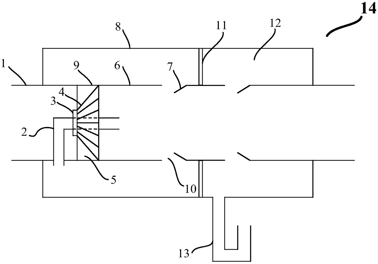
[0027] use as figure 1 The horizontally arranged gas-liquid separation device 14 shown is used for gas-liquid separation after the condensed circulating gas in the process of producing linear low density polyethylene (LLDPE). Wherein, the internal diameter of inner cylinder 6 is 600mm, is divided into 3 pipe sections, and the width of liquid separator 10 is 50mm, and the diameter expansion ratio of the second pipe section is 1.10, and the internal diameter of outer cylinder 8 is 1000mm, and the external diameter of cover cylinder 9 is 590mm, the inner diameter of the elbow 2 is 80mm, the diameter of the blind plate 3 is 200mm, the number of swirl blades 4 is 15, the thickness of the blades is 5mm, and the projection overlap ratio is -0.5.

[0028] The liquid-containing gas stream comprising hydrogen, nitrogen, methane, ethane, ethylene, hexene and isopentane at a pressure of 2.4 MPa and a temperature of 47° C. passes through the gas-liquid separation device 14 at a speed of 35...

Embodiment 2

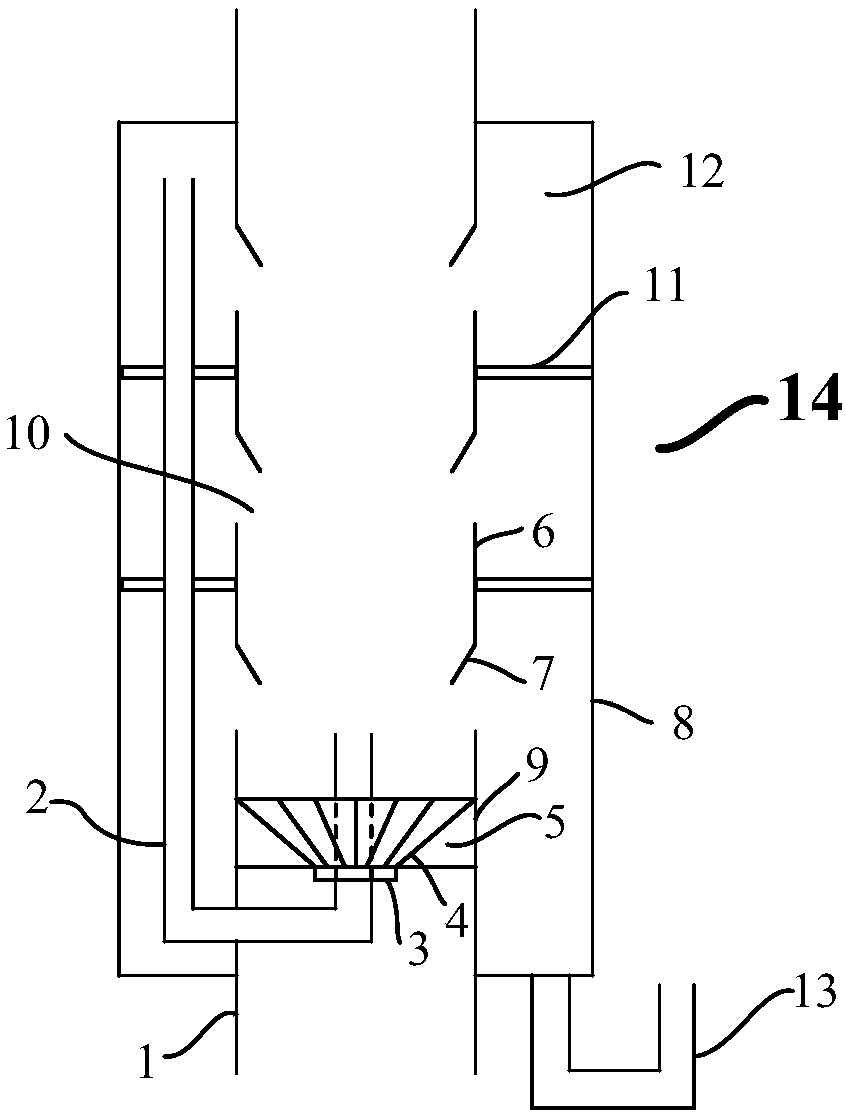
[0030] use as figure 2 The vertically arranged gas-liquid separation device 14 shown is used for gas-liquid separation after the condensed circulating gas in the process of producing linear low-density polyethylene (LLDPE). Wherein, the internal diameter of inner cylinder 6 is 700mm, is divided into 4 pipe sections, the width of liquid separator 10 is 80mm, the diameter expansion ratio of the 2nd and the 3rd pipe section is 1.05, the internal diameter of outer cylinder 8 is 1100mm, cover cylinder 9 The outer diameter of the pipe is 690mm, the inner diameter of the elbow 2 is 100mm, the diameter of the blind plate 3 is 180mm, the number of swirl blades 4 is 18, the thickness of the blades is 5mm, and the projection overlap ratio is -0.6.

[0031] A gas flow comprising hydrogen, nitrogen, methane, ethane, ethylene, hexene and isopentane with a pressure of 2.4 MPa and a temperature of 52° C. passes through the gas-liquid separation device 14 at a speed of 25 m / s. In the gas flo...


PUM

PropertyMeasurementUnit
thicknessaaaaaaaaaa
thicknessaaaaaaaaaa
thicknessaaaaaaaaaa

Abstract

The invention relates to a gas-liquid separation device, and belongs to the field of chemical machinery. The gas-liquid separation device comprises an inner cylinder, an outer cylinder, and a rotational flow part; the inner cylinder is connected with a supply pipeline for conveying liquid-containing airflow and is composed of a plurality of pipe sections, liquid dividing troughs are formed betweenthe pipe sections, and the drainage resistance is reduced; the outer cylinder sleeves the exterior of the inner cylinder with a certain gap, a closed annular cavity is formed between the inner cylinder and the outer cylinder, and a U-shaped liquid-sealed drainage pipe is arranged on the outer cylinder; the rotational flow part is arranged between the upstream side of the inner cylinder and the supply pipeline; the outer cylinder is connected with a low-pressure zone of the center of the inner cylinder through a blind plate of the rotational flow part via an elbow pipe; gas of the outer cylinder is sucked by using the pressure difference between the inner cylinder and the outer cylinder, and the pressure of the outer cylinder is reduced. The gas-liquid separation device has the characteristics of high gas-liquid separation efficiency and low pressure drop, and has strong adaptability to different production devices.

Description

technical field [0001] The invention relates to a gas-liquid separation device, in particular to a gas-liquid separation device used in the condensed state process of olefin polymerization. technical background [0002] Gas-liquid separation technology is widely used in various industrial processes such as petrochemical industry, tail gas recovery, wet dust removal, and waste heat utilization of flue gas. For example, in the condensed state process of olefin polymerization, the separation of condensate in the circulating gas stream has an important impact on the heat removal capacity of the reactor, the temperature range distribution and the product properties. Condensate is usually separated based on gravity, inertia, centrifugation, etc. and their combinations. Among them, centrifugal separators are widely used because of their advantages of high separation efficiency and small pressure drop. Patent ZL 201010617116.1 discloses a cyclone plate separator for gas phase polye...

Claims


Application Information

Patent Timeline
Patent Type & Authority Applications(China)
IPC IPC(8): B01D45/16
CPCB01D45/16
Inventor 王可钦孙婧元田思航陈阳黄正梁杨遥叶健王靖岱蒋斌波廖祖维阳永荣
Owner ZHEJIANG UNIV
Why Eureka
Try Eureka