An Intelligent Control Method for Rodless Oil Well Lifting System

An intelligent control and oil well technology, applied in pump control, earthwork drilling, wellbore/well components, etc., can solve the problems of rodless pump application range limitation, difficulty in reducing speed, damage to rubber stator, etc., to avoid dry grinding and rapid Effects of damage, low energy consumption cost, and reduced running resistance

Active Publication Date: 2020-11-03
LIAONING RUIBANG PETROLEUM TECH DEVCO
View PDF8 Cites 0 Cited by
  • Summary
  • Abstract
  • Description
  • Claims
  • Application Information

AI Technical Summary

Problems solved by technology

The electric submersible centrifugal pump has high speed and large displacement, but it is difficult to reduce the speed, so it can only be used in oil wells with sufficient liquid supply
Under the condition of lack of liquid, the submersible screw pump is easy to dry grinding, which will quickly damage the rubber stator, causing the pump efficiency to drop sharply until it is damaged
[0004] It is precisely because of the above-mentioned defects that the application range of rodless pumps is greatly limited. Therefore, the production wells in most oil fields still use beam pumping units with rod pumps to lift oil.

Method used


Image

  • An Intelligent Control Method for Rodless Oil Well Lifting System
  • An Intelligent Control Method for Rodless Oil Well Lifting System
  • An Intelligent Control Method for Rodless Oil Well Lifting System

Examples


Embodiment Construction

[0048] The present invention will be further elaborated below in conjunction with the accompanying drawings of the description.

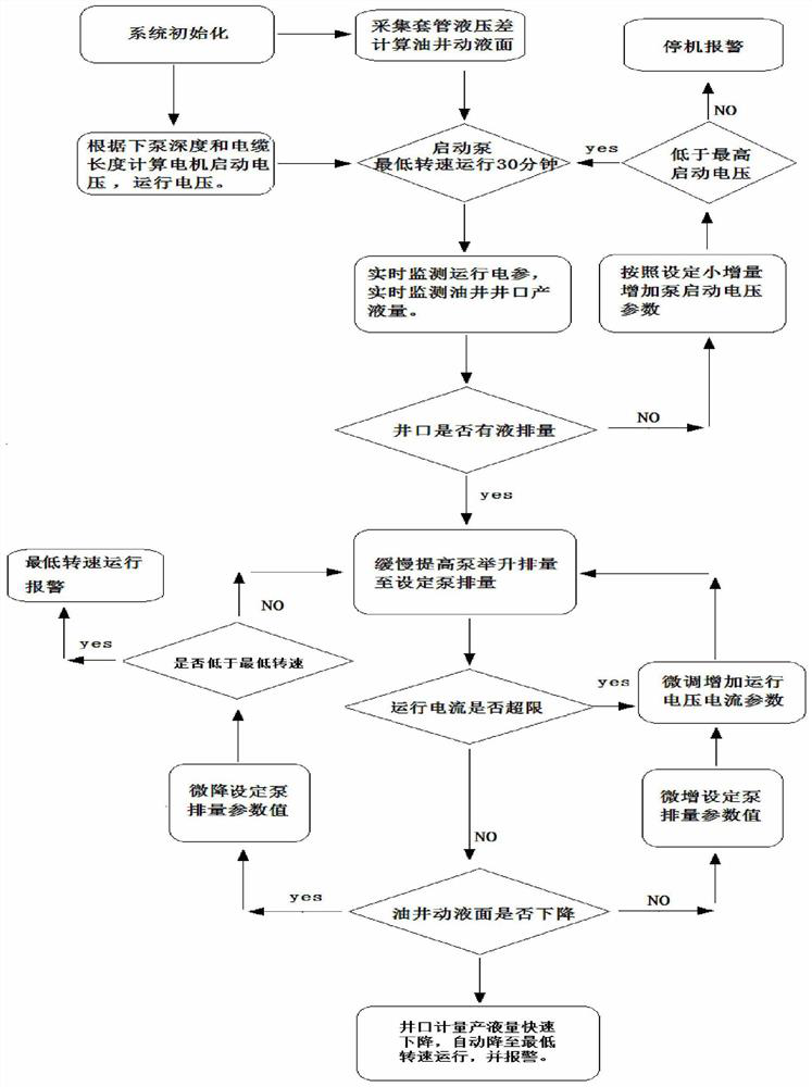
[0049] Such as figure 1 As shown, an intelligent control method of a rodless oil well lifting system of the present invention comprises the following steps:

[0050] After the system is initialized, the hydraulic pressure difference of the rodless lifting system is collected to calculate the oil well liquid level;

[0051] After starting the submersible screw pump to run for a specified time, real-time monitoring of operating electrical parameters and wellhead liquid production of oil wells;

[0052] When there is liquid displacement at the wellhead, increase the pump lift displacement to the set pump lift displacement;

[0053] When the operating current of the submersible screw pump does not exceed the limit, it is judged whether the dynamic liquid level of the oil well has dropped;

[0054] If the dynamic liquid level of the oil well drops due...


PUM


Abstract

The invention relates to an intelligent control method for a rodless lifting system for an oil well. The intelligent control method comprises the steps that after a system is initialized, the hydraulic difference of the rodless lifting system is collected, and the liquid level of the oil well is calculated; a submersible progressing cavity pump is started and operated for a specified time, and then operating electrical parameters and the liquid production capacity of an oil well wellhead are monitored in real time; when the liquid displacement occurs on the wellhead, the pump lifting displacement is increased to the set pump displacement; when the operating current of the submersible progressing cavity pump does not exceed the limit, whether the working liquid level of the oil well is descended or not is judged; if the working liquid level of the oil well is descended due to the large pump lifting displacement, the set displacement parameter value of the submersible progressing cavitypump is decreased; whether the current rotating speed of the submersible progressing cavity pump reaches the lowest rotating speed or not is judged; and if the current rotating speed of the submersible progressing cavity pump does not reach the lowest rotating speed, the step that the pump lifting displacement is increased to the set pump displacement is executed. According to the intelligent control method, the problem of impedance compensation matching of cables of different oil well depths is solved through an adaptive voltage and current uplift technology, thus an underground submersible motor obtains good electricity energy matching, the operating period is long, the lifting efficiency is high, and the energy consumption cost is low.

Description

technical field [0001] The invention relates to a rodless lifting system control technology applied in oil wells, in particular to an intelligent control method for a rodless lifting system of a suspended submersible screw pump. Background technique [0002] At present, the oil production pumps used in oil fields at home and abroad can be roughly divided into two categories, namely rod pumps and rodless pumps; most of the rod pumps in the prior art are reciprocating plunger pumps, and the pumping units on the ground use the motor The rotary motion of the pump becomes up and down reciprocating motion and is transmitted to the plunger of the oil pump submerged in the oil layer through the sucker rod, so that the plunger reciprocates up and down in the pump barrel to realize oil pumping. Due to the long sucker rod string, the elastic deformation of the sucker rod caused by the pump load and the self-weight of the sucker rod is very large, which in turn leads to a large stroke l...

Claims


Application Information

Patent Timeline
Patent Type & Authority Patents(China)
IPC IPC(8): E21B43/12E21B47/047E21B47/00F04C11/00F04C14/00F04C14/28
CPCE21B43/121E21B47/00E21B47/047F04C11/00F04C14/00F04C14/28
Inventor 赵小平郝学成周警卫郝佳艺
Owner LIAONING RUIBANG PETROLEUM TECH DEVCO
Why Eureka
Try Eureka