Novel ash removing device and method for low-low-temperature coal economizer

A technology of low and low temperature economizer and ash cleaning device, which is applied in the direction of cleaning heat transfer device, combustion method, feed water heater, etc. Boiler economy and safety, the ability of flue gas to carry fly ash is weakened, etc., to achieve the effect of reducing flue ash accumulation, improving ash carrying capacity, and low cost

Pending Publication Date: 2018-11-13
CHINA HUADIAN ENG +1
View PDF6 Cites 3 Cited by
  • Summary
  • Abstract
  • Description
  • Claims
  • Application Information

AI Technical Summary

Problems solved by technology

At present, the operating load of most power plant boiler units in my country is low. Therefore, the flue gas flow rate in the flue is lower than the design value (9m / s), and the ability of the flue gas to carry fly ash is weakened, resulting in serious ash accumulation in this horizontal section, which directly affects the economy of the boiler. sex and security
So far, there has been no reasonable solution to the serious problem of low-load ash accumulation in the low-low temperature economizer system
The main equipment of the system includes: warehouse pump, air compressor, air compression tank, gasification fan, ash unloading system, ash hopper heater, steam system, etc.; the system is relatively complex, costly and occupies a large area

Method used


Image

  • Novel ash removing device and method for low-low-temperature coal economizer
  • Novel ash removing device and method for low-low-temperature coal economizer
  • Novel ash removing device and method for low-low-temperature coal economizer

Examples


Embodiment 2

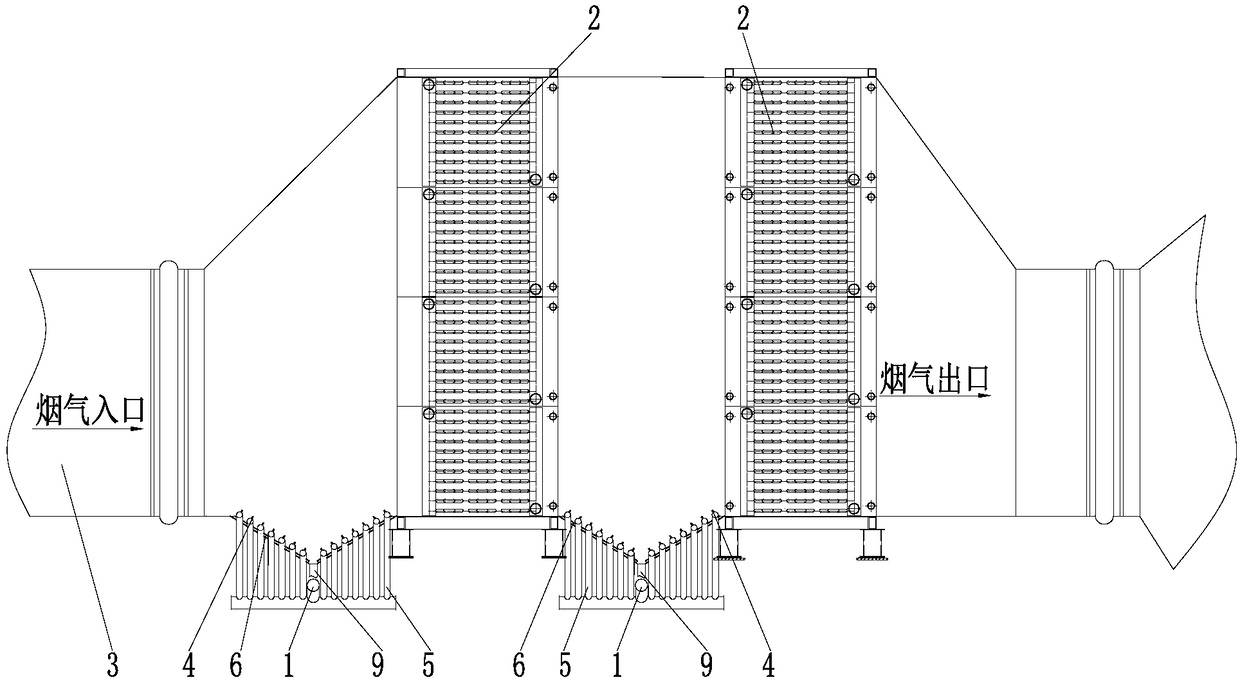
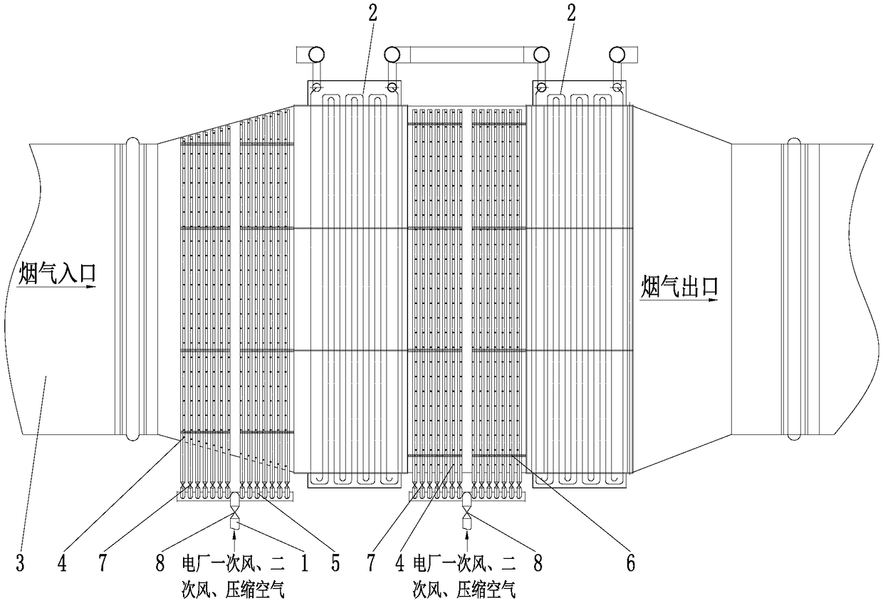
[0028] Embodiment 2: as Figure 1-Figure 3As shown, the soot cleaning device of the new low-low temperature economizer, wherein a heat exchanger group is arranged in the flue of the low-low temperature economizer, and the heat exchanger group includes m vertically arranged (that is, the flue section is from top to bottom Direction setting) set heat exchange modules 2, n heat exchange modules 2 arranged horizontally (ie set flue gas flow direction), m and n are both natural numbers greater than 1, specifically, m is 4, n is 2. A set of ash removal devices is installed in the third-stage flue at the entrance of the low-temperature economizer before the dust collector, and another set of ash removal devices is installed between the heat exchanger groups. The ash removal devices all include the ash removal main pipe 1, Soot cleaning nozzle 4, soot cleaning branch pipe 5, branch pipe valve 7 and main pipe valve 8, one end of the several ash cleaning branch pipes 5 is connected with...

Embodiment 3

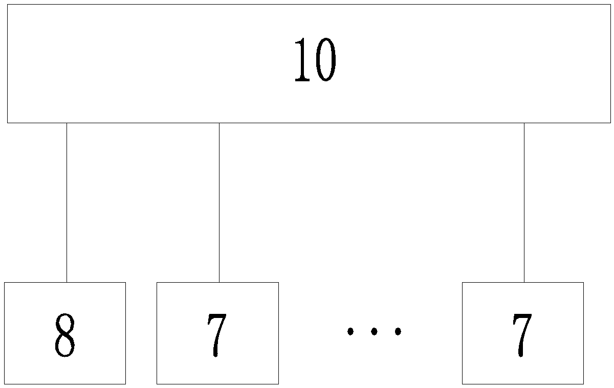
[0030] Embodiment 3: as Figure 1-Figure 2 As shown, the ash removal method of the new low-low temperature economizer adopts the aforesaid ash removal device of the new low-low temperature economizer, including the following method: the control system 10 adjusts the opening quantity and opening frequency of the branch valve 7 according to the load signal of the boiler , also adjust the opening frequency of the main pipe valve 8, so that when the boiler load is low and the ash-carrying capacity of the flue gas is weak, in order to prevent ash accumulation, the branch pipe valve 7 and the main pipe valve 8 need to be opened, so that the ash cleaning main pipe 1 The purge medium enters the flue through the soot removal branch pipe 5 and the soot removal nozzle 4 to sweep upwards, and the flue gas is suspended by the air volume and wind pressure, so that the dust will not fall to the bottom plate of the flue, reducing the dust load of the flue, The deposited fly ash is carried awa...

Embodiment 4

[0031] Embodiment 4: as Figure 1-Figure 2 As shown, the soot cleaning device of the new low-low temperature economizer, wherein a heat exchanger group is arranged in the flue of the low-low temperature economizer, and the heat exchanger group includes m vertically arranged (that is, the flue section is from top to bottom Direction setting) heat exchange modules 2, n heat exchange modules 2 arranged in a horizontal arrangement (that is, flue gas flow direction setting), m and n are both natural numbers greater than 1. A set of ash removal devices is installed in the third-stage flue at the entrance of the low-temperature economizer before the dust collector, and another set of ash removal devices is installed between the heat exchanger groups. The ash removal devices all include the ash removal main pipe 1, Soot cleaning nozzle 4, soot cleaning branch pipe 5, branch pipe valve 7 and main pipe valve 8, one end of the several ash cleaning branch pipes 5 is connected with a soot ...


PUM


Abstract

The invention relates to a novel ash removing device and method for a low-low-temperature coal economizer, and belongs to the field of industrial flue gas purification and waste heat recovery of coal-fired power station boilers, industrial boilers and the like. The ash removing device comprises ash removing main tubes, ash removing nozzles, ash removing branch tubes, branch tube valves and main tube valves, one ends of the plurality of ash removing branch tubes are connected with the ash removing main tubes, the main tube valves are arranged on the ash removing main tubes, the plurality of ashremoving nozzles with upward openings are further arranged on each ash removing branch tube, and each ash removing branch tube is provided with the corresponding branch tube valve. According to the novel ash removing device and method, in a system, the turbulence of the flue gas is adjusted by adopting the mode of opening and closing the branch tube valves and the main tube valves, the flue gas is in a suspended state through the air volume and the air pressure, dust cannot fall to a bottom plate of a flue, and the uniformity of the flue flow field of the section of the low-low-temperature coal economizer is improved. The invention further provides the novel ash removing method of the low-low-temperature coal economizer. The resistance loss of a boiler unit can be effectively reduced, theenergy loss of the flue gas can be reduced, and the heat exchange effect can be enhanced.

Description

technical field [0001] The invention relates to a novel ash cleaning device and method for a low-low temperature economizer, and belongs to the fields of industrial flue gas purification and waste heat recovery of coal-fired power station boilers, industrial boilers, and the like. Background technique [0002] Coal-fired power plant boilers have a large proportion of exhaust heat loss during operation, accounting for more than 50% of the total boiler heat loss. Some thermal power plants operate with exhaust gas temperatures that are often higher than the design value. Therefore, reducing the exhaust gas temperature of power plant boilers has important practical significance for energy saving and emission reduction. Under this background, low and low temperature economizers have been widely used. At present, low and low temperature economizers are often used to recover and reuse the waste heat of the discharged high temperature flue gas. The heat recovered by low and low temp...

Claims


Application Information

Patent Timeline
Patent Type & Authority Applications(China)
IPC IPC(8): F23J3/02F28G1/16F28G15/00F22D1/04
CPCF22D1/04F23J3/02F28G1/166F28G15/003F23J2700/001
Inventor 张锡乾肖隽吴冲杨彭飞
Owner CHINA HUADIAN ENG
Why Eureka
Try Eureka