
Neodymium ion doped vanadate crystal laser

A technology of neodymium ions and vanadate, applied in the field of lasers, can solve the problems of high light intensity, high laser threshold, complex laser structure and design, etc.

Active Publication Date: 2018-11-30
SHANDONG UNIV
View PDF7 Cites 2 Cited by
  • Summary
  • Abstract
  • Description
  • Claims
  • Application Information

AI Technical Summary

Problems solved by technology

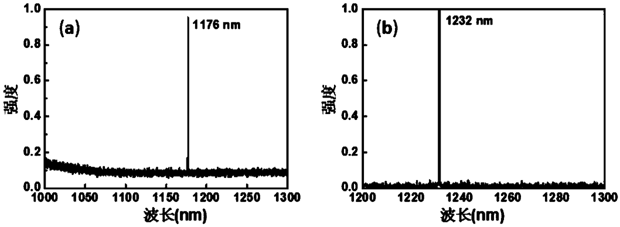
The above-mentioned methods for obtaining lasers with wavelengths of 1176nm and 1170nm are all stimulated Raman scattering techniques, which are a third-order nonlinear optical process, and the electrical polarization of the medium is not linearly related to the incident light intensity, but a third-order power Series relationship, photons participate in the process of forming laser, it is photon-phonon interaction, the required light intensity is larger, the laser threshold is higher, and the laser structure and design are more complicated

Method used


Image

  • Neodymium ion doped vanadate crystal laser
  • Neodymium ion doped vanadate crystal laser
  • Neodymium ion doped vanadate crystal laser

Examples


Embodiment 1

[0040] A vanadate crystal laser doped with neodymium ions, with a structure such as figure 1 As shown, the excitation source 1, the focusing system 2, the input cavity mirror 3, the laser dielectric crystal 4, and the output cavity mirror 5 are arranged in sequence along the optical path. The input cavity mirror 3 and the output cavity mirror 5 constitute a laser resonant cavity. Excitation source 1 is a laser diode laser with emission center wavelength of 808nm; focusing system 2 is composed of two convex lenses with a focal length of 3cm, focusing system 2 has a focal length of 3cm and a focusing ratio of 1:1; input cavity mirror 3 is a flat mirror It is plated with a dielectric film A that is highly transparent to 800nm-890nm, 1000nm-1080nm, 1320nm-1400nm and highly reflective to 1123nm-1300nm; the laser dielectric crystal 4 is a yttrium vanadate crystal with a neodymium ion doping concentration of 0.25wt%, The length of the crystal in the light direction is 6mm, and the ligh...

Embodiment 2

[0043] A vanadate crystal laser doped with neodymium ions, as described in Example 1, the difference is that the excitation source 1 is a laser diode laser with an emission center wavelength of 880nm, and other conditions and components are the same as those described in Example 1. . When the laser in this embodiment is used, the quantum loss is small, which is conducive to high-efficiency laser output. .

Embodiment 3-5

[0045] A vanadate crystal laser doped with neodymium ions, as described in Example 1, the difference is laser dielectric crystal 4, and the length of the yttrium vanadate crystal doped with neodymium ions is 4mm, 8mm and 4mm respectively. 10mm, other conditions and components are the same as those described in Example 1.


PUM

PropertyMeasurementUnit
Wavelengthaaaaaaaaaa

Abstract

The invention provides a neodymium ion doped vanadate crystal laser. The neodymium ion doped vanadate crystal laser comprises an excitation source, a focusing system, a laser resonant cavity and a laser dielectric crystal. A neodymium ion doped vanadate crystal serves as the laser dielectric crystal; a diode laser emitting a laser with the central wavelength being 808 nm or 880 nm serves as the excitation source; the laser resonant cavity is composed of an input cavity lens and an output cavity lens, and the input cavity lens and the output cavity lens are plated with suitable film structuresto obtain output of a laser at the waveband of 1123-1300 nm; and the laser dielectric crystal is located between the input cavity lens and the output cavity lens, and the excitation source, the focusing system and the laser resonant cavity are sequentially arrayed along a light path. The neodymium ion doped vanadate crystal laser only refers to the laser effect, an emission spectrum is expanded through the electron-phonon coupling effect in the neodymium ion doped vanadate crystal, and the neodymium ion doped vanadate crystal laser has the advantages of being low in laser threshold value, highin conversion efficiency, simple in design and the like.

Description

Technical field [0001] The invention relates to a vanadate crystal laser doped with neodymium ions and belongs to the technical field of lasers. Background technique [0002] Lasers of different wavelengths have different application ranges and requirements, and the wavelength of the laser is determined by the intrinsic energy level of the activated ions in the gain medium. Currently based on rare earth ions (such as Nd 3+ , Yb 3+ Etc.) The radiation of electrons in the intrinsic energy levels has maturely realized 946nm, 912nm, 1064nm, 1340nm, 960nm and other wavelength lasers (Applied Physics B, 70,769, 2000; Applied Physics B, 86, 65, 2007; patents) Document CN101728757A). In the wavelength range of 1100-1300nm, Nd 3+ The intrinsic emission of ions may achieve laser emission with stimulated radiation near 1110nm. For example, the use of neodymium-doped yttrium aluminum garnet crystal (abbreviation: Nd:YAG) stimulated radiation can obtain 1112nm and 1123nm lasers (Opt. Lett 3...

Claims


Application Information

Patent Timeline
IPC IPC(8): H01S3/08H01S3/0941H01S3/16H01S3/30
CPCH01S3/08H01S3/0941H01S3/1611H01S3/1671H01S3/30
Inventor 于浩海张怀金房倩楠马长勤韩学坤
Owner SHANDONG UNIV
Learn More