Light slice fluorescence microscopic imaging method and device based on relocation

A microscopic imaging and repositioning technology, applied in the field of optical imaging, can solve the problems of limiting the range of imaging field of view, reducing lateral resolution, increasing sample photobleaching, etc., without reducing the field of view, improving axial resolution, The effect of not reducing the imaging speed

Active Publication Date: 2018-12-07
ZHEJIANG UNIV
View PDF8 Cites 8 Cited by
  • Summary
  • Abstract
  • Description
  • Claims
  • Application Information

AI Technical Summary

Problems solved by technology

For example, make an excitation light sheet thin enough that the axial resolution is no longer dependent on the numerical aperture (NA) of the added objective, but this thinner light sheet will occur faster away from the beam waist. The diffusion limits the imaging field of view; the excitation beam can also be modulated into a Bessel beam to avoid the reduction of the field of view, but this will introduce illumination outside the focal plane and increase the photobleaching of the sample; It is possible to image the sample multiple times at different detection angles by rotating the sample, and then use a computer to fuse the multiple views, but this approach reduces both imaging speed and lateral resolution

Method used


Image

  • Light slice fluorescence microscopic imaging method and device based on relocation
  • Light slice fluorescence microscopic imaging method and device based on relocation
  • Light slice fluorescence microscopic imaging method and device based on relocation

Examples


Embodiment 1

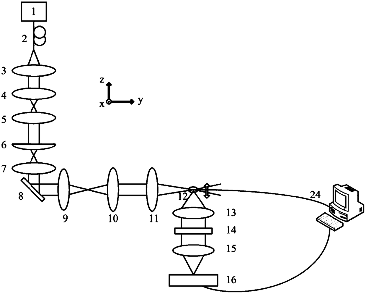
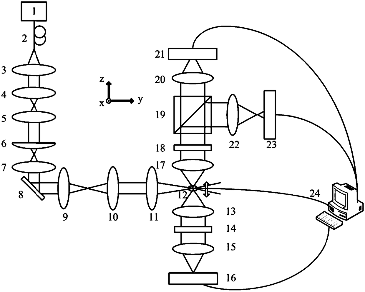
[0048] see figure 2 , the repositioning-based optical section fluorescence microscopic imaging device of the present embodiment includes a laser 1, a single-mode optical fiber 2, a collimating lens 3, a telescope composed of a convex lens 4 and a convex lens 5, a cylindrical lens 6, and a first relay lens 7. Mirror 8, second relay lens 9, third relay lens 10, illumination objective lens 11, fluorescent sample 12, first detection objective lens 13, first optical filter 14, first tube lens 15, first CCD Camera 16, second detection objective lens 17, second optical filter 18, half mirror 19, second tube lens 20, second CCD camera 21, third tube lens 22, third CCD camera 23, computer 24.

[0049] use figure 2 With the imaging device shown, the specific steps for implementing the repositioning-based optical sectioning fluorescence microscopy imaging method are as follows:

[0050] (1) The laser light emitted by the laser 1 is filtered by the single-mode fiber 2, and then the la...

Embodiment 2

[0064] see Figure 4 , the repositioning-based optical section fluorescence microscopic imaging device of the present embodiment includes a laser 1, a single-mode optical fiber 2, a collimating lens 3, a telescope composed of a convex lens 4 and a convex lens 5, a cylindrical lens 6, and a first relay lens 7. Mirror 8, second relay lens 9, third relay lens 10, illumination objective lens 11, fluorescent sample 12, first detection objective lens 13, first optical filter 14, first tube lens 15, first CCD Camera 16, second detection objective lens 17, half-transparent mirror 25, vibrating mirror 26, pinhole I27, photoelectric tube I28, pinhole II29, photoelectric tube II30, computer 24.

[0065] use Figure 4 The specific process of implementing the repositioning-based optical sectioning fluorescence microscopy imaging method for the imaging device shown is as follows:

[0066] (1) The laser light emitted by the laser 1 is filtered by the single-mode fiber 2, and then the laser b...

Embodiment 3

[0078] The repositioning-based optical section fluorescence microscopy imaging method provided in this embodiment has been included in Embodiment 1 or Embodiment 2, and will not be repeated here.


PUM


Abstract

The invention discloses a light slice fluorescence microscopic imaging method and device based on relocation, and belongs to the technical field of optical imaging, the light slice fluorescence microscopic imaging device comprises a laser, a cylindrical mirror, a sample stage carrying a fluorescent sample, and a detection system collecting fluorescence emitted by the fluorescent sample, the laser,the cylindrical mirror and the sample stage arranged along the optical path in turn, the detection system includes a first detector, a beam splitter, a second detector, and a third detector, the detection system also includes a processor coupled to the detection system and the sample stage, the processor controls the sample stage to move along Z-axis in a fixed step length, compares a fluorescence image I1 and a fluorescence image I2 to obtain position information of each part of the fluorescence on the Z-axis, and the fluorescence information in a fluorescence image I0 is repositioned and three-dimensionally reconstructed according to the position information to obtain a three-dimensional imaging result of the fluorescent sample. The axial resolution of imaging can be improved without reducing the range of an imaging view field, increasing photobleaching of the sample, and reducing of imaging speed.

Description

technical field [0001] The invention relates to the technical field of optical imaging, in particular to a repositioning-based optical section fluorescence microscopic imaging method and device. Background technique [0002] With the development of science and technology, people have put forward higher and higher requirements for the resolution of microscopic structures and microscopic imaging of biological functions. In addition to the requirement of high resolution, the detection time and detection range also need to be faster and wider. [0003] Fluorescence microscopy imaging, as a means of observing specific events in the microscopic world, has long been of great significance to modern life science research. Especially in developmental biology, regenerative medicine, tissue engineering and other fields that require observation and analysis of multicellular samples, three-dimensional and all-round imaging is very important for analyzing the structure and biological char...

Claims


Application Information

Patent Timeline
Patent Type & Authority Applications(China)
IPC IPC(8): G01N21/64
CPCG01N21/6428
Inventor 匡翠方王晓娜黎文柔张乘风刘旭李海峰
Owner ZHEJIANG UNIV
Why Eureka
Try Eureka