Liquefied natural gas (LNG) cold energy air separation system and air separation method

A technology of liquefied natural gas and air separation system, which is applied in the field of air separation using the cold energy of liquefied natural gas, can solve problems such as increased comprehensive unit energy consumption, large inlet flow, hidden dangers of device safety, etc., to reduce equipment investment and solve energy problems The effect of high consumption and increased dosage

Pending Publication Date: 2019-01-04
邢仁钊
View PDF2 Cites 8 Cited by
  • Summary
  • Abstract
  • Description
  • Claims
  • Application Information

AI Technical Summary

Problems solved by technology

Looking at LNG cold energy air separation plants at home and abroad, there are generally phenomena that the process organization is too complicated, and the energy consumption is high, the implementation is not easy, the operation control is inconvenient, or the safety and reliability are not good.
For example, multiple compressors, multiple expanders, separation tanks, etc. are used, and there are many heat exchanger channels, especially when LNG is high pressure, the heat exchanger channels are many, resulting in a sharp increase in cost
In addition, the process organization is complicated, and areas with many electrical components such as valves and measurement points need to be explosion-proof, which brings hidden dangers to the safety of the device.
[0003] Chinese patent application specification CN 101571340A discloses an air separation system that utilizes the cold energy of liquefied natural gas. The patent uses a three-stage low-temperature air intake cycle nitrogen compressor and an ethylene glycol cooling system, but the liquid oxygen product is mainly obtained by relying on The high-pressure subcooled liquid nitrogen in the low-pressure oxygen and LNG-nitrog

Method used


Image

  • Liquefied natural gas (LNG) cold energy air separation system and air separation method
  • Liquefied natural gas (LNG) cold energy air separation system and air separation method

Examples


Embodiment 1

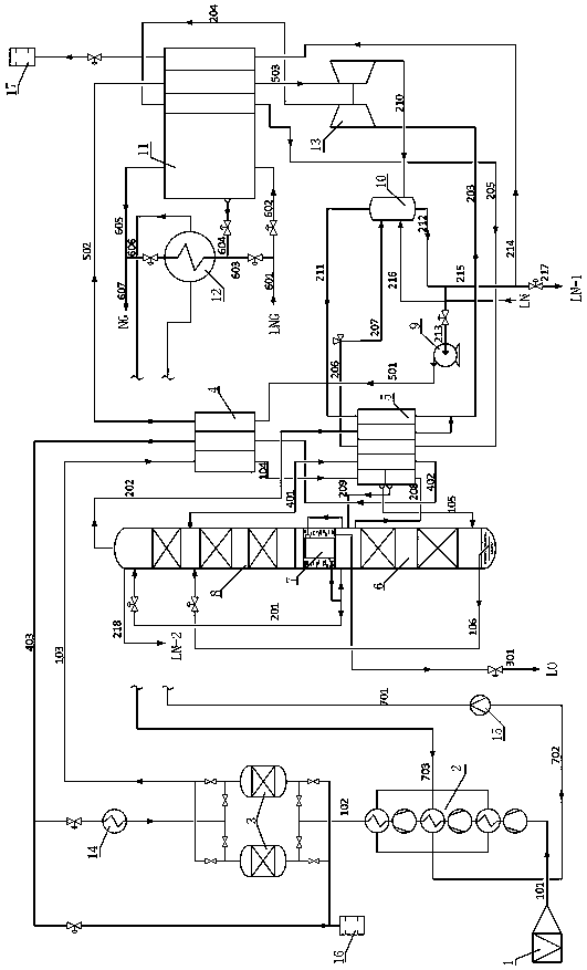
[0054] An air separation system utilizing the cold energy of liquefied natural gas, comprising an air separation unit, an LNG cold energy utilization unit and an ethylene glycol solution circulation cooling unit;

[0055] Described ethylene glycol solution circulation cooling unit comprises LNG-ethylene glycol heat exchanger 12 and ethylene glycol solution circulation pump 15;

[0056] The LNG cold energy utilization unit includes a circulating liquid nitrogen pump 9, an LNG-nitrogen heat exchanger 11, a gas-liquid separator 10, a liquid booster expander 13 and a vent silencer 17;

[0057] The air separation unit comprises a self-cleaning air filter 1, an air compressor 2, a molecular sieve 3, a regeneration gas heater 14, a main heat exchanger 4, a liquefaction heat exchanger 5, a rectifying tower and a vent silencer 16, and the refining Distillation tower comprises lower tower 6, main condensing evaporator 7 and upper tower 8 three parts.

[0058] In the air separation unit...

Embodiment 2

[0078] An air separation system utilizing the cold energy of liquefied natural gas to carry out an air separation method, comprising the following steps:

[0079] a) After the raw air passes through the self-cleaning filter 1 to remove most of the solid impurities, it enters the air compressor 2 for compression, and the purified air 103 is obtained after removing impurities such as water and hydrocarbons through the molecular sieve system 3;

[0080] b) The pure air 103 is cooled in the main heat exchanger 4 by exchanging heat with the dirty nitrogen gas 402 drawn from the upper part of the upper tower 8 and provided with cooling capacity and initially reheated in the liquefaction heat exchanger 5, and the high-pressure circulating liquid nitrogen 501 liquefaction. The dirty nitrogen gas 403 completely reheated in the main heat exchanger is connected to the purification system 3 for regeneration gas and cold blowing gas;

[0081] c) The liquefied air 104 provides cooling capa...


PUM


Abstract

The invention discloses a liquefied natural gas (LNG) cold energy air separation system and air separation method. The air separation system comprises an air separation unit, an LNG cold energy utilization unit and an ethylene glycol solution circulating and cooling unit. Through the new process organization form that a circulating liquid nitrogen pump is used for replacing a low-temperature circulating nitrogen compressor, production energy consumption of the LNG cold energy air separation system is substantially reduced, the extraction rate of oxygen and argon is high, the liquefaction ratioof a nitrogen product reaches up to 100%, and the additional value is high; moreover, a liquid nitrogen reverse current cold supplement mode is matched with LNG cold energy changes, and the LNG coldenergy air separation system has fewer requirements for an LNG receiving station and is high in universality. Compared with an existing LNG cold energy air separation technology, the LNG cold energy air separation system and air separation method have the beneficial effects that the comprehensive energy consumption is reduced by 40% or more, and the unit energy consumption is reduced by 60% or more; moreover, the unit energy consumption is still lower than that in the prior art under extreme production reduction conditions, and the cost advantages are quite obvious.

Description

technical field [0001] The invention relates to an air separation method, in particular to an air separation method utilizing the cold energy of liquefied natural gas. Background technique [0002] As one of the chemical energy sources, natural gas has been gradually promoted as the main energy pillar after coal and oil due to its huge reserves and low pollution, and has broad application prospects. The trade forms of natural gas mainly include pipeline transportation and LNG (liquefied natural gas) transportation. Before LNG enters the pipeline network of natural gas users, it needs to be gasified from a liquefied state to normal temperature. The gasification process will release a huge amount of cold energy. By making full use of the gasification cold energy of LNG, the air separation device can significantly reduce power consumption, increase liquid production, and improve the competitiveness of products in the market. The economic benefits are very obvious. However, sin...

Claims


Application Information

Patent Timeline
IPC IPC(8): F25J3/04F25J5/00
CPCF25J3/04018F25J3/04157F25J5/007F25J3/0406F25J3/04084F25J3/04193F25J3/04224F25J3/04272F25J3/04357F25J2205/02F25J2210/62F25J2230/04F25J2250/20F25J2250/40F25J2250/42F25J2270/904
Inventor 邢仁钊
Owner 邢仁钊
Why Eureka
Try Eureka