Special-shaped hole machining method and special-shaped hole

A processing method and special-shaped hole technology, applied in metal processing equipment, manufacturing tools, welding equipment, etc., can solve the problems of thermal influence, low efficiency of complete electric discharge machining, hole making, etc., and achieve the effect of improving shape and dimensional accuracy

Inactive Publication Date: 2019-01-11
AVIC BEIJING AERONAUTICAL MFG TECH RES INST
View PDF7 Cites 8 Cited by
  • Summary
  • Abstract
  • Description
  • Claims
  • Application Information

AI Technical Summary

Problems solved by technology

[0005] The efficiency of complete electric discharge machining is low, and thermally induced defects such as recasting layers will occur, and it is impossible to complete the hole making on parts whose surface is first prepared with a non-conductive ceramic-based thermal barrier coating;
[0006] The process and equipment of laser-EDM secondary processing are complicated, and the accuracy of secondary alignment is not easy to guarantee;
[0007] Although the millisecond pulse laser cutting method has high efficiency, the processing shape is limited. It is necessary to ensure that the cutting process along the surface of the hole wall of the diffusion section does not destroy the shape integrity of the special-shaped hole. It is necessary to strictly control the cutting depth or take protective measures such as filling protective materials, and Millisecond long-pulse laser cutting with large energy will cause severe thermal effects, resulting in thermally induced defects such as recast layers and microcracks

Method used


Image

  • Special-shaped hole machining method and special-shaped hole
  • Special-shaped hole machining method and special-shaped hole
  • Special-shaped hole machining method and special-shaped hole

Examples


Embodiment 1

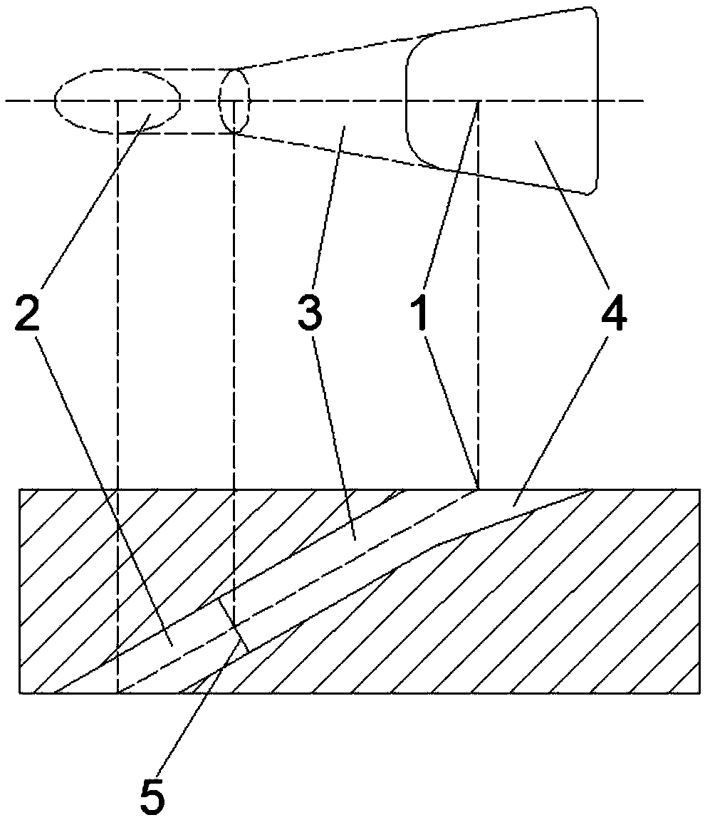
[0046] A special-shaped hole processing method:

[0047] The scanning galvanometer is a two-dimensional scanning galvanometer or a three-dimensional scanning galvanometer that can achieve dynamic focusing. The laser light source is selected from one of femtosecond, picosecond and nanosecond pulse lasers. axis parallel.

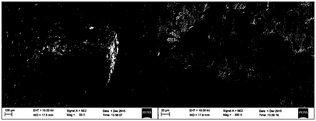
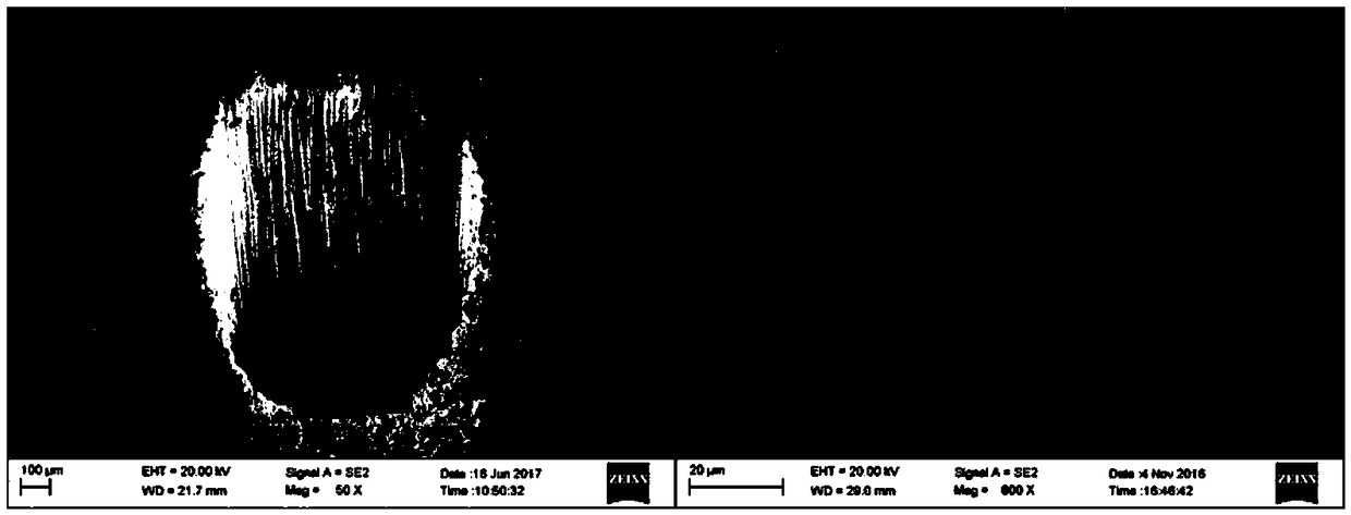
[0048] First process the initial through hole: eg figure 1As shown, the laser is focused on the center of the hole on the surface of the workpiece 1, and the galvanometer scanning filling method is used to process the initial through hole whose exit diameter is smaller than the required aperture.

[0049] Then process the peripheral area 4 of the diffusion section 3: that is, only the area that does not overlap with the circular hole of the diffusion section is processed, and the processing path adopts the three-dimensional digital analog slicing method to generate a filling processing path, and the processing sequence is from the inside to the outside, that ...

Embodiment 2

[0057] A special-shaped hole processing method:

[0058] The special-shaped hole is processed on the workpiece with thermal barrier coating on the surface.

[0059] Other steps are the same as in Embodiment 1.


PUM


Abstract

The invention discloses a special-shaped hole machining method and a special-shaped hole and relates to the technical field of laser machining. According to the method, femtosecond or picosecond or nanosecond pulse laser is adopted, and a mode completely based on scanning galvanometer filling machining is provided. The method comprises the steps that firstly, a through hole smaller than the hole diameter requirement is machined so that gasification objects and fusion objects formed in the machining process can be discharged and re-coagulation objects are prevented from depositing; then, roughmachining of a special-shaped hole diffusion section is conducted; then, the laser focusing position is adjusted, broaching is conducted on the basis of a dust discharge through hole, and a cylindrical through hole meeting the hole diameter requirement is machined; and finally, the focus position is precisely adjusted, and the diffusion section is machined layer by layer. By means of the special-shaped hole machining method and the special-shaped hole, heat-induced defects such as recasting layers, microcracks, coating collapse and the like generated in the process that in the prior art, a special-shaped hole is machined, and in particular, the special-shaped hole is machined in a workpiece with the surface coated with a thermal barrier coating are avoided; and in addition, the shape and dimension precision of the special-shaped hole are improved.

Description

technical field [0001] The invention relates to the technical field of laser machining holes, in particular to a method for machining a special-shaped hole and the special-shaped hole. Background technique [0002] Special-shaped holes have long been used in the cooling structure of aero-engine turbine blades due to their better film cooling effect. [0003] The special-shaped hole is mainly composed of a through hole and a diffusion section. According to the structural characteristics of the special-shaped hole, various processing methods have been adopted at home and abroad. The earliest method adopted is electric discharge machining, but the efficiency is low; in order to improve efficiency, two-step processing is adopted, that is, laser processing of cylindrical holes, and electric discharge forming electrode processing of the diffusion section of the hole; there are also millisecond pulse laser direct cutting processing. Method, the processing of the diffusion section ...

Claims


Application Information

Patent Timeline
Patent Type & Authority Applications(China)
IPC IPC(8): B23K26/382B23K26/70
CPCB23K26/382B23K26/702
Inventor 张晓兵蔡敏马宁纪亮张伟焦佳能
Owner AVIC BEIJING AERONAUTICAL MFG TECH RES INST
Why Eureka
Try Eureka