
Method for measuring liquid viscosity in capillary tube based on micro volume sample measurement

A test method and capillary technology, applied in the direction of DC flow characteristics measurement, etc., can solve the problems of blank, slow heating and cooling, large sample volume, etc., and achieve good practicability, reduce consumption, and small sample consumption.

Active Publication Date: 2019-02-15
成都珂睿科技有限公司
View PDF11 Cites 2 Cited by
  • Summary
  • Abstract
  • Description
  • Claims
  • Application Information

AI Technical Summary

Problems solved by technology

However, the temperature control generally uses a water bath, which is bulky, slow to rise and fall in temperature, and the test takes a long time and manual operation is complicated. The most critical thing is that it is impossible to measure the viscosity of non-Newtonian fluids (viscosity changes with flow rate) at different shear rates.
The constant rate capillary method for measuring viscosity is more common in polymer rheometers. Although it can measure the viscosity of non-Newtonian fluids at different shear rates, its structure is complex, bulky, consumes a lot of samples, and it is difficult to clean after use.
[0003]The biggest drawbacks of existing viscosity detection methods are that the required sample volume is large, the temperature control is not precise enough, the non-Newtonian fluid cannot be measured, and the detection efficiency is low
At present, there is no fluid viscosity detection equipment that can accurately and quickly measure a small amount or even a small amount (<1ml) of samples, especially for the viscosity measurement of non-Newtonian fluids at different shear rates, there is still a blank

Method used


Image

  • Method for measuring liquid viscosity in capillary tube based on micro volume sample measurement
  • Method for measuring liquid viscosity in capillary tube based on micro volume sample measurement
  • Method for measuring liquid viscosity in capillary tube based on micro volume sample measurement

Examples


Embodiment 1

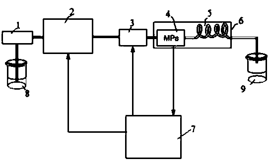
[0064] A capillary viscosity testing method based on micro sample measurement, the flow path is filled with a flow medium, and then the sample fluid is introduced, and the flow medium pushes the sample to flow through the capillary 5; when the viscosity of the sample fluid is small or the sample fluid is compressed under high pressure When the small volume is negligible, set the volume V of the sample liquid to be greater than the capillary 5 volume V c ; When the viscosity of the sample fluid is very high and the volume of the sample fluid compressed under high pressure cannot be ignored, then multiple injections are performed and the volume V of each injection liquid is less than the capillary 5 volume V c .

[0065] as attached figure 1 As shown, the flow medium is placed in the liquid storage bottle 8. After the flow medium passes through the degasser 1, it enters the constant flow high-pressure pump 2. The constant flow high-pressure pump 2 is regulated by the controlle...

Embodiment 2

[0074] This embodiment is optimized on the basis of embodiment 1, such as Figure 5 As shown, when the volume V of the sample liquid is greater than the volume V of the capillary c When the sample is completely filled with the capillary 5, the pressure difference between the two ends of the capillary 5 is ΔP, and the radius r, inner diameter d, length L, and flow rate Q of the capillary 5 can be calculated according to Poiseuille's law. shear rate shear stress

[0075] Such as Image 6 As shown, when the viscosity of the sample fluid is very high and the volume of the sample fluid compressed under high pressure is not negligible, two injections of different volumes are carried out, and the injection volumes are V 1 , V 2 , the pressure drop change of the sample from entering the capillary 5 to the process of completely excluding the capillary 5 is ΔP, and the time for the sample to pass through the capillary 5 is ΔT; the volume difference of the sample under high press...

Embodiment 3

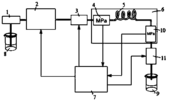
[0084] This embodiment is optimized on the basis of embodiment 1, such as figure 2 As shown, in order to expand the pressure range of the test system, a second pressure sensor 10 and a back pressure regulating device 11 can be added and connected to the outlet side of the capillary 5 . The back pressure regulating device 11 is controlled by the controller 7 and can generate a specified flow resistance. The second pressure sensor 10 returns the pressure value to the controller 7 in real time at a certain sampling rate.

[0085] The sampling system is responsible for introducing a specified volume of sample into the high-pressure fluid pipeline, which can be realized by using a flow-through sampling valve widely used in liquid chromatography or other structures with similar functions. The temperature control system is used to ensure that the temperature of the sample is constant when passing through the capillary 5, which can be realized by using a thermostat 6 or a water bath ...


PUM


Abstract

The invention discloses a method for measuring the liquid viscosity in a capillary tube based on micro volume sample measurement, comprising the following steps of: filling the flow path with the flowing medium and then introducing the sample fluid, which is pushed by the flowing medium through the capillary tube; setting the volume V of the injection liquid to be larger than the volume Vc of thecapillary tube when the viscosity of the sample fluid is small or the sample fluid is compressed under high pressure so that the reduced volume thereof is negligible; and performing multiple injections and ensuring that the volume V of each injection liquid is smaller than the volume Vc of the capillary tube when the viscosity of the sample fluid is large and the sample fluid is compressed under high pressure but the reduced volume is not negligible. According to the method for measuring the liquid viscosity in a capillary tube based on micro volume sample measurement, the consumption of the sample is reduced by the setting of the flowing medium; the viscosity of the sample can be calculated without standard sample calibration, which also contribute to the consumption reduction of the sample; the sample consumption of the invention is small, thereby facilitating the testing of the micro volume sample and broadening the test range of the sample; and the method is suitable for the viscosity determination of non-Newtonian fluids and is excellent in practicability.

Description

technical field [0001] The invention belongs to the technical field of liquid viscosity measurement, in particular to a capillary viscosity testing method based on micro sample measurement. Background technique [0002] Viscosity is an important physical parameter of fluid. Common viscometers include rotational viscometer, falling ball viscometer, vibrating viscometer, capillary viscometer, etc. The first three methods use the movement resistance of the fluid to achieve viscosity measurement, which requires a large amount of samples and complicated viscosity calculation methods. The most widely used capillary viscometer is represented by the Ubbelohde viscometer. Its working principle is to count the liquid flow at both ends of the capillary with constant pressure difference, that is, the constant pressure method. It has simple structure, good precision and easy operation, and is widely used in the viscosity detection of polymer solutions, blood plasma, gasoline, diesel and...

Claims


Application Information

Patent Timeline
IPC IPC(8): G01N11/06G01N11/08
CPCG01N11/06G01N11/08
Inventor 孙亮刘枫王宇董军
Owner 成都珂睿科技有限公司
Learn More