

Malodorous gas comprehensive treatment device
A technology for comprehensive treatment and malodorous gas, applied in air quality improvement, dispersed particle separation, chemical instruments and methods, etc. Reduce the footprint of the module, avoid the circulation of the circulating fluid, and ensure the effect of uniformity
- Summary
- Abstract
- Description
- Claims
- Application Information
AI Technical Summary
Problems solved by technology
Method used
Image

Examples
Embodiment
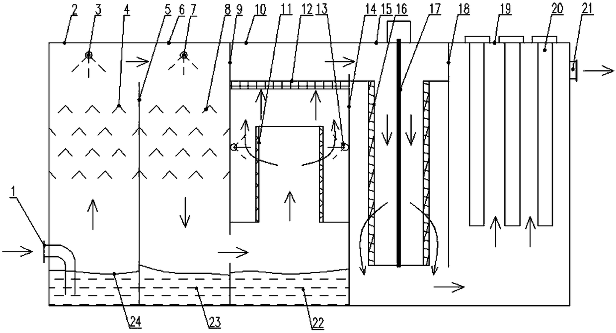
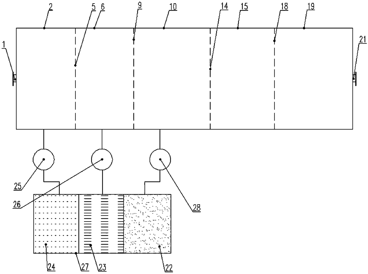
[0038] see figure 1 and figure 2, a kind of malodorous gas comprehensive treatment device in the illustration is the preferred scheme of the present invention. This scheme mainly realizes the purification process of malodorous gas through alkali washing section, pickling section, biological purification section, adsorption purification section and photocatalytic oxidation section. Ultra-low emissions can be achieved. These five processes are respectively realized in a closed box, specifically including the box body of the alkali washing section 2, the box body of the pickling section 6, the box body of the biological purification section 10, and the box body of the adsorption purification section arranged side by side. 15 and the photocatalytic oxidation section casing 19, wherein the adjacent alkali washing section casing 2 and the pickling section casing 6 are separated by the first partition 5, and the adjacent pickling section casing 6 and the biological purification sect...
PUM
 Abstract
Description
Claims
Application Information