High-power slab green laser

A laser and high-power technology, applied in the direction of lasers, laser components, laser components, etc., can solve the problems of reduced beam quality, small pump spot, difficult to apply, etc., to achieve simple structural design, suppress thermal effects, and high work efficiency Effect

Pending Publication Date: 2019-02-22
SHANDONG UNIV
View PDF4 Cites 4 Cited by
  • Summary
  • Abstract
  • Description
  • Claims
  • Application Information

AI Technical Summary

Problems solved by technology

This type of laser has the advantages of simple structure, stability, and compactness. This method has the advantages of good mode matching and high efficiency, and is suitable for watt-level low-power laser output. However, the pump light of this structure is focused in the laser crystal. Under the requirements of the requirements, the pump spot is small (on the order of hundreds of microns), the heat generated during the laser process is mainly concentrated in this area, and the direction of the temperature gradient is perpendicular to the direction of light propagation. When operating under thermal load conditions, It will produce serious thermal lens effect and optical distortion

Method used


Image

  • High-power slab green laser
  • High-power slab green laser
  • High-power slab green laser

Examples


Embodiment 1

[0063] Embodiment 1: A high-power slab green laser that realizes the output of a 545nm green laser

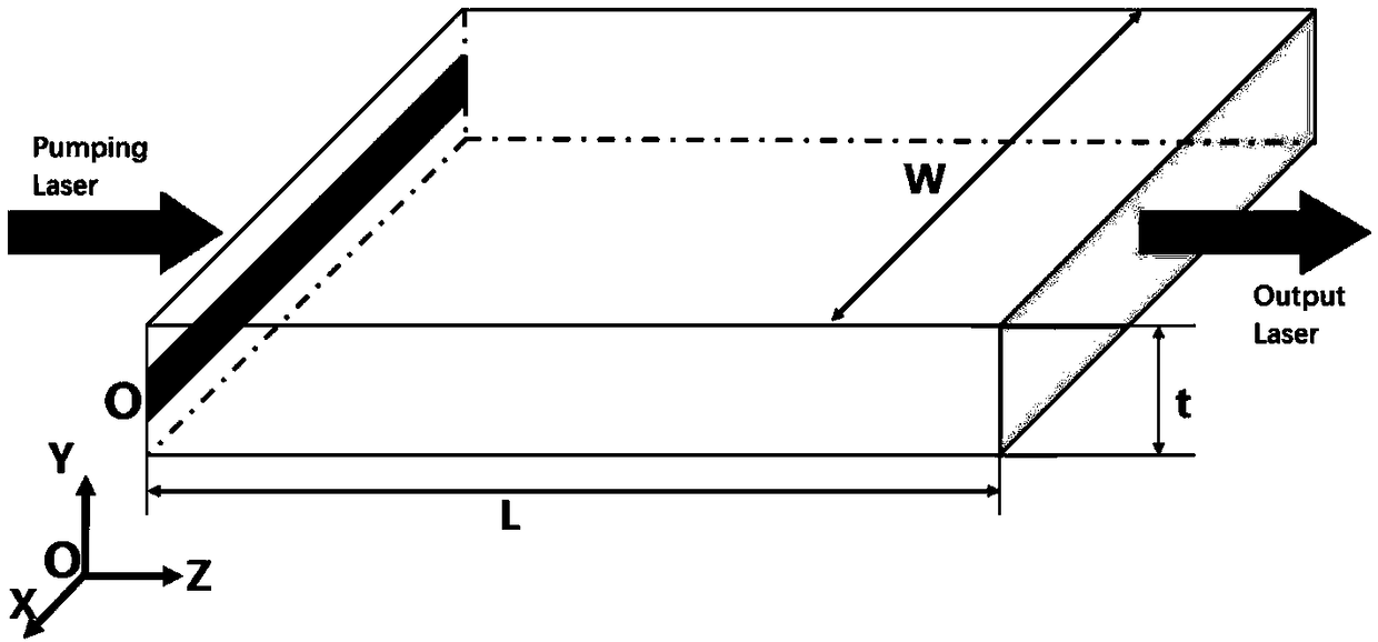
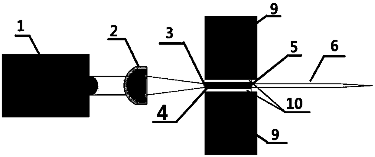
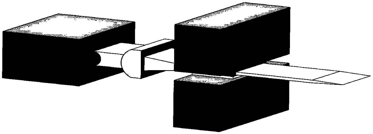
[0064] A high-power slab green laser with a structure such as figure 2 , 3 As shown, the pumping source 1, the focusing system 2, and the self-frequency doubling crystal 4 are sequentially arranged along the optical path. The pump source 1 is a laser diode array with an emission center wavelength of 808nm; the focusing system 2 is composed of a plano-convex cylindrical mirror with a focal length of 6.35cm; the self-frequency doubling crystal 4 is calcium borate with a neodymium ion doping concentration of 8at.% Oxygen gadolinium crystal, the length of the crystal in the light-passing direction is 8mm, and the light-passing surface is 12×1mm 2 Rectangular, and polished, the tangent is cut along the phase matching direction with the largest effective nonlinear coefficient at 1090nm. The best phase matching direction is: the main axis direction (Z axis) with the largest refract...

Embodiment 2

[0067] A high-power slab green laser, as described in Embodiment 1, the difference is that the pump source 1 is a laser diode array with an emission center wavelength of 880nm, and other conditions and components are consistent with those described in Embodiment 1, which can realize 545nm band green laser output. When the laser in this embodiment is used, the quantum defect is small, which is beneficial to the high-efficiency output of the laser.

Embodiment 3-5

[0069] A high-power slab green laser, as described in Embodiment 1, the difference is that the self-frequency doubling crystal 4, the length of the light-transmitting direction of the neodymium ion-doped calcium borate-gadolinium-oxygen crystal is 4mm, 6mm and 10mm respectively, Other conditions and components are consistent with those described in Example 1. Both achieve 545nm band green laser output.


PUM

PropertyMeasurementUnit
Center wavelengthaaaaaaaaaa
Lengthaaaaaaaaaa
Thicknessaaaaaaaaaa

Abstract

The invention provides a high-power slab green laser. The high-power slab green laser includes a pump source, a focusing system, a laser resonator and a self-frequency doubling crystal. The self-frequency doubling crystal is a neodymium ion doped calcium borate rare earth salt crystal cut into a slab shape along a direction of a maximum non-principal effective nonlinear coefficient of the crystal.Phase matching of different wavelengths is realized by changing a tangential direction of the crystal so as to realize laser output in 545 nm or 550 nm band. The pump source is a laser diode array having an emission center wavelength of 808 nm or 880 nm. An input cavity mirror and an output cavity mirror are coated with suitable film systems so as to obtain high-power laser output in the 545 nm or 550 nm band. The laser of the invention has the advantages of low laser threshold, high conversion efficiency and output power, and simple laser structure.

Description

technical field [0001] The invention relates to a high-power slab green laser and belongs to the technical field of lasers and nonlinear crystal devices. Background technique [0002] Green light refers to light with a wavelength of 500 nm to 560 nm. Green lasers have been used in both military and civilian fields such as laser display, indication, and blinding weapons. There are two main ways to generate practical green laser light: based on indium (In) doped GaN semiconductor (InGaN) emission and Nd 3+ Doped laser crystal frequency doubled laser. Among them, for InGaN semiconductors, the emission wavelength depends on the concentration of In. At present, the emission wavelength of commercial InGaN semiconductors is below 520nm; while Nd 3+ Doped crystals, such as commonly used yttrium vanadate and yttrium aluminum garnet, have emission peaks around 1064nm, and when they are frequency-multiplied, high-power, high-efficiency 532nm lasers can be obtained. Looking at the g...

Claims


Application Information

Patent Timeline
IPC IPC(8): H01S3/16H01S3/109H01S3/094H01S3/042H01S3/04H01S3/105
CPCH01S3/0405H01S3/042H01S3/094038H01S3/105H01S3/1095H01S3/16H01S3/1603H01S3/1666
Inventor 张怀金于浩海杜金恒王继扬
Owner SHANDONG UNIV
Why Eureka
Try Eureka