High-load artificial wetland system with enhanced nitrogen and phosphorus removal function
A constructed wetland system, nitrogen and phosphorus removal technology, applied in the field of enhanced nitrogen and phosphorus removal high-load constructed wetland system, can solve the problems of high labor intensity, depletion, and exceeding the standard of the project, to avoid hydraulic short circuit, ensure treatment effect, prolong The effect of migration path
- Summary
- Abstract
- Description
- Claims
- Application Information
AI Technical Summary
Problems solved by technology
Method used
Image
Examples
Embodiment 1
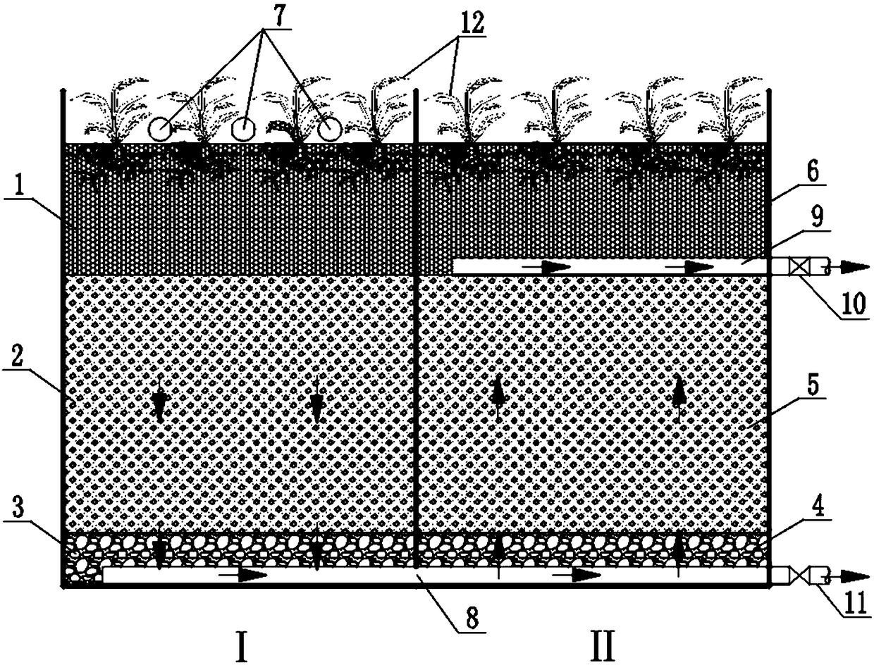
[0040] The hydraulic load of this embodiment is 0.40m3 / (m 2 d). The structure of the high-load constructed wetland system for enhanced nitrogen and phosphorus removal is as follows: figure 1 shown. In this embodiment, the area ratio of wetland I and wetland II is 1:1, wetland I is downward flow, and wetland II is upward flow. The pool body of the artificial wetland system is a brick-concrete structure, and the bottom and the pool wall are treated with anti-seepage. The water collecting and distributing pipe 8 collects the sewage treated in the wetland I and evenly distributes it in the wetland II. Wherein the water collecting and distributing pipe 8 is connected to an emptying pipe 11 with a ball valve leading to the outside of the pool, which is used for emptying the wetland or discharging mud. The bottom of the fourth packing layer 6 is provided with a water collection and drainage pipe 9 for discharging the treated sewage out of the system. The water collection and dr...
Embodiment 2
[0045] The hydraulic load of this embodiment is 1.20m 3 / (m 2 d). The structure of the high-load constructed wetland system for enhanced nitrogen and phosphorus removal is as follows: figure 1 shown. The arrangement sequence of the packing layers in this example is basically the same as that in Example 1, the main difference is that the area ratio of wetland I and wetland II is 2:1, and the composition and thickness of each packing layer are also different. The first packing layer 1 and the fourth packing layer 6 both have a thickness of 35 cm, and the fillers are mixed fillers of zeolite and crushed stone (volume ratio 2:1), and the particle size ranges from 0.4 to 0.8 cm. The thickness of the second packing layer 2 and the third packing layer 5 are both 80cm, and the fillers are mixed fillers of steel slag, gravel and pyrite (the mixing ratio is 4:2:1), and the particle size ranges from 0.5 to 1.2cm. The first crushed stone layer 3 and the second crushed stone layer 4 bo...
PUM
| Property | Measurement | Unit |
|---|---|---|
| thickness | aaaaa | aaaaa |
| particle diameter | aaaaa | aaaaa |
| thickness | aaaaa | aaaaa |
Abstract
Description
Claims
Application Information
 - R&D
- Intellectual Property
- Life Sciences
- Materials
- Tech Scout
- Unparalleled Data Quality
- Higher Quality Content
- 60% Fewer Hallucinations
Browse by: Latest US Patents, China's latest patents, Technical Efficacy Thesaurus, Application Domain, Technology Topic, Popular Technical Reports.
© 2025 PatSnap. All rights reserved.Legal|Privacy policy|Modern Slavery Act Transparency Statement|Sitemap|About US| Contact US: help@patsnap.com

