
Condensation heat exchanger for treating waste gas high in moisture content and intensified heat exchanger method

A technology of condensing heat exchangers and high moisture content, which is applied in the direction of heat exchanger types, indirect heat exchangers, heat exchange equipment, etc., which can solve the problems of increasing costs, occupying more space, and low removal efficiency, so as to achieve saving The effect of low investment, low investment and high heat exchange efficiency

Pending Publication Date: 2019-03-01
江苏双良冷却系统有限公司
View PDF1 Cites 1 Cited by
  • Summary
  • Abstract
  • Description
  • Claims
  • Application Information

AI Technical Summary

Problems solved by technology

Although this patent uses a collection tank with a special structure, the collected condensed water is used as the water source of the flushing system of the wet electrostatic precipitator to realize the automatic online flushing function, but its cathode system is arranged outside the condensation heat exchanger and requires a separate Anode systems, which greatly increase cost, take up space, and are less efficient at removing pollutants such as fine particles (2.5 microns and below) and aerosols
[0006] Therefore, the prior art has the following deficiencies: 1. The existing condensing heat exchanger has low heat transfer efficiency and high cost; 2. Adding wet electrostatic precipitator not only increases investment, but also takes up more space; 3. Wet electric precipitator The removal efficiency of pollutants such as fine particles (2.5 microns and below) and aerosols is low

Method used


Image

  • Condensation heat exchanger for treating waste gas high in moisture content and intensified heat exchanger method
  • Condensation heat exchanger for treating waste gas high in moisture content and intensified heat exchanger method

Examples


Embodiment Construction

[0022] specific implementation plan

[0023] The present invention is described below in conjunction with accompanying drawing and specific embodiment:

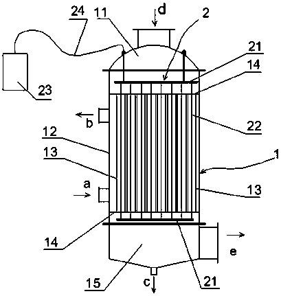
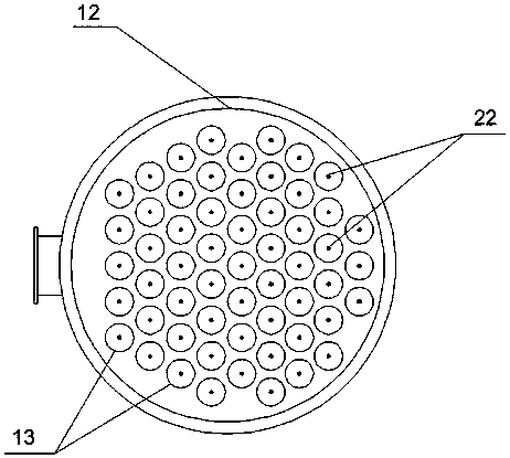
[0024] Such as Figure 1~2 As shown, a condensing heat exchanger for treating waste gas with high moisture content includes a condensing heat exchanger body 1, the condensing heat exchanger body 1 is vertical, and the upper end cover 11 is provided with a waste gas inlet d , the right side wall of the lower end cover 15 is provided with an exhaust gas outlet e, the bottom of the lower end cover 15 is provided with a condensate outlet c, and the bottom of the left side wall of the cylinder 12 is provided with a cooling medium inlet a, and the cylinder 12 A cooling medium outlet b is provided on the top of the left side wall, and a plurality of heat exchange tubes 13 are provided inside the condensing heat exchanger body 1, and the heat exchange tubes 13 are made of conductive metal or non-metallic material. Titanium alloy ma...


PUM


Abstract

The invention discloses a condensation heat exchanger for treating waste gas high in moisture content and an intensified heat exchanger method. The condensation heat exchanger comprises a condensationheat exchanger body (1). The condensation heat exchanger body (1) is internally provided with multiple heat exchange tubes (13). The heat exchange tubes (13) are made of electrically-conductive metalor non-metal materials. The heat exchanger further comprises a static electricity generating device (2). The static electricity generating device (2) comprises a cathode fixing bracket (21), cathodewires (22), a power source (23) and a connecting wire (24). The cathode wires (22) are arranged in the heat exchange tubes (13). The cathode wires (22) form a cathode, and the heat exchange tubes (13)form an anode. The cathode wires (22) and the heat exchange tubes (13) form a static electric field in the heat exchange tubes (13), so that the waste gas flows in the heat exchange tubes (13), and acooling medium flows outside the heat exchange tubes (13). By means of the condensation heat exchanger, the dedusting / defogging efficiency can be improved in the condensation process; and the condensation heat exchanger has the advantages that the investment is low, the heat exchange efficiency and the dedusting / defogging efficiency are high, and the equipment space is saved.

Description

technical field [0001] The invention relates to the field of condensation heat exchange, in particular to a condensation heat exchanger and an enhanced heat exchange method for treating waste gas with high moisture content. Background technique [0002] In industries such as electric power, iron and steel, coking and building materials, waste gas with high moisture content is often discharged through chimneys. For example, after the flue gas produced by coal-fired boilers is sent into the chimney through wet desulfurization, its moisture content reaches saturation. After these exhaust gases are discharged into the atmosphere, it is easy to form a high-humidity environment in local areas, which provides the conditions to promote the conversion of fine particles in the air into "smog". The pollutants contained in the exhaust gases will also have an impact on environmental pollution. [0003] In order to avoid visible white smoke when the chimney discharges the exhaust gas (cal...

Claims


Application Information

Patent Timeline
Patent Type & Authority Applications(China)
IPC IPC(8): F28D7/16F28F21/08B03C3/16B03C3/49B03C3/41
CPCF28D7/16F28F21/086B03C3/16B03C3/41B03C3/49
Inventor 薛海君江瀚
Owner 江苏双良冷却系统有限公司
Learn More