Method for detecting cytochrome c in living cell based on Raman-fluorescent dual-mode probe
A dual-mode probe and detection method technology, applied in the fields of nanomaterials and life sciences, can solve problems such as hindering applications and weak Raman scattering intensity, and achieve accurate and reliable results, significant Raman enhancement, and significant fluorescence quenching effects Effect
- Summary
- Abstract
- Description
- Claims
- Application Information
AI Technical Summary
Problems solved by technology
Method used
Image
Examples
Embodiment 1
[0060] The synthesis route of gold seeds is as follows:
[0061] 50 μL of 25 mM HAuCl 4 Add the solution to 4.7 mL of 0.1 M CTAC solution and inject 300 μL of freshly prepared pre-cooled 10 mM NaBH under vigorous stirring 4 solution, the solution changed from light yellow to orange and then stood at room temperature for 2h to consume excess NaBH 4 ,spare.
Embodiment 2
[0063] The synthetic route of AuNTs is as follows:
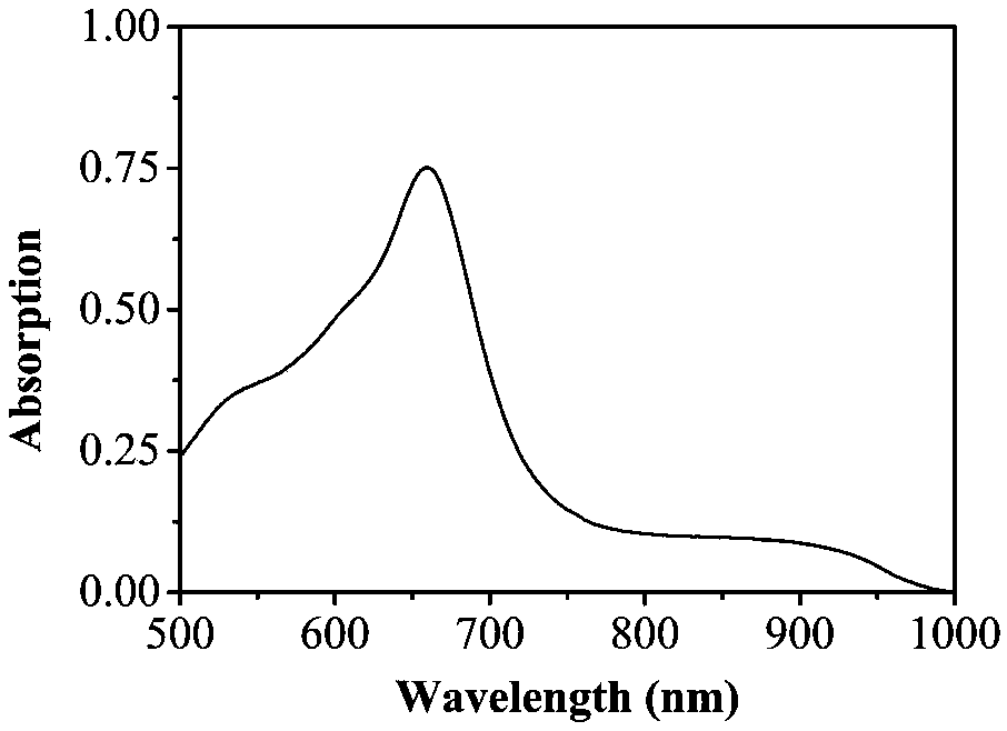
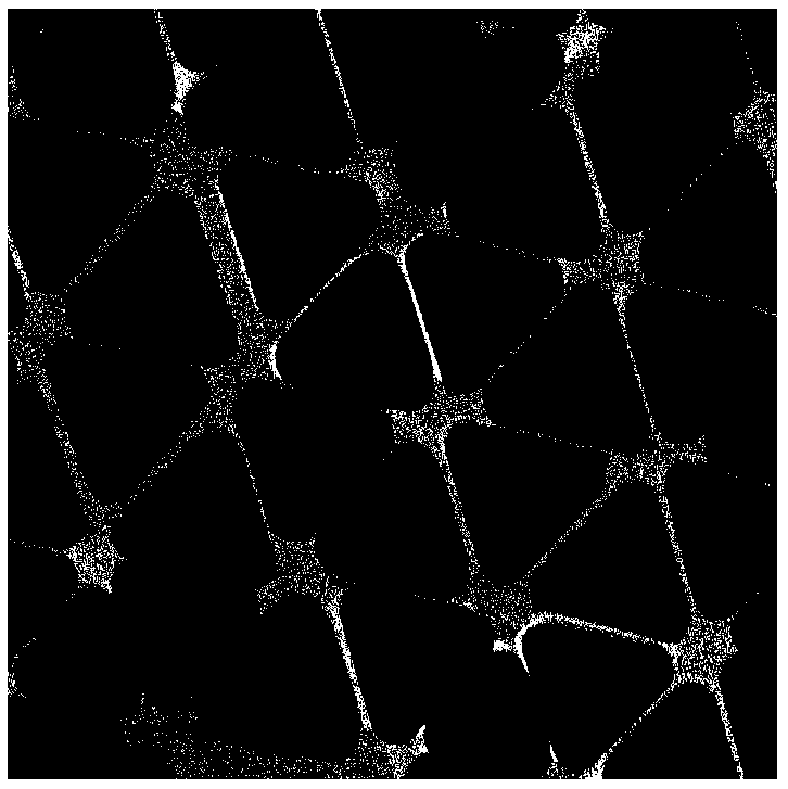
[0064] After the prepared seeds were diluted 10 times with 0.1M CTAC solution, two growth solutions were prepared: (A) 1.6mL of 0.1M CTAC solution was added to 8mL of ultrapure water, and then 40μL of 50mM HAuCl was added 4 and 15μL 10mM NaI; (B) 500μL 50mM HAuCl 4 Added to 40 mL of 0.05M CTAC, followed by 300 μL of 10 mM NaI. Growth solution A was used to grow CTAC-capped seeds into larger nanoparticles, while growth solution B was used for the growth of triangular sheets. Add 40 and 400 μL of 0.1M AA solutions to growth solutions A and B, respectively, and stir until the two solutions turn from light yellow to completely transparent, indicating that Au III Reverted to Au I . Then 100 μL of diluted seeds was added to growth solution A, and after stirring for no more than 5 s, 3.2 mL of this solution was immediately added to growth solution B and stirred for 5 s. Finally, the growth solution B was allowed to stand at ro...
Embodiment 3
[0066] Preparation of Raman-fluorescent dual-mode probes:
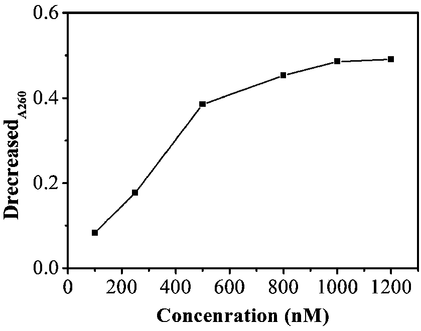
[0067] Add SH-PEG-COOH solution to the resuspended AuNTs and keep stirring for 1 h, and centrifuge at 3000 rpm for 10 min to remove excess unreacted reagents. Place the DNA solution in a water bath at a temperature higher than Tm for 5 min to activate the DNA. Then the Cyt c aptamer DNA1 solution was added to the AuNTs so that the final DNA1 concentrations were 100, 250, 500, 800, 1000 and 1200 nM ( image 3 ). It is well known that the intensity of absorbance decrease represents the affinity between NP and DNA to some extent. The DNA aqueous solution has a typical absorption band (about 260nm), and the decrease of this value can be used to prove that the nanoparticles are modified by DNA. As shown, ΔA260 increased significantly with increasing DNA1 concentration. When the concentration reaches 1000nM, ΔA260 is almost unchanged. Therefore, the optimal concentration of DNA1 final concentration is 1000 nM. The mix...
PUM
 Abstract
Description
Claims
Application Information
 - R&D
- Intellectual Property
- Life Sciences
- Materials
- Tech Scout
- Unparalleled Data Quality
- Higher Quality Content
- 60% Fewer Hallucinations
Browse by: Latest US Patents, China's latest patents, Technical Efficacy Thesaurus, Application Domain, Technology Topic, Popular Technical Reports.
© 2025 PatSnap. All rights reserved.Legal|Privacy policy|Modern Slavery Act Transparency Statement|Sitemap|About US| Contact US: help@patsnap.com


