Non-catalytic reforming reactor and technology thereof

A reforming reactor, reforming reaction technology, applied in chemical/physical/physical-chemical stationary reactors, detailed information of chemical/physical/physical-chemical reactors, control/adjustment processes, etc., can solve the problem of reducing production efficiency. , the mechanical and electronic characteristics of the complex control of the injection device, the increase in cost, etc., to achieve the effect of reducing the soot rate, high productivity, and reducing heat loss

A reforming reactor, reforming reaction technology, applied in chemical/physical/physical-chemical stationary reactors, detailed information of chemical/physical/physical-chemical reactors, control/adjustment processes, etc., can solve the problem of reducing production efficiency. , the mechanical and electronic characteristics of the complex control of the injection device, the increase in cost, etc., to achieve the effect of reducing the soot rate, high productivity, and reducing heat loss

CN109569490AActive Publication Date: 2019-04-05TAIYUAN UNIV OF TECH

Image

  • Non-catalytic reforming reactor and technology thereof
  • Non-catalytic reforming reactor and technology thereof
  • Non-catalytic reforming reactor and technology thereof

Examples


Embodiment 1

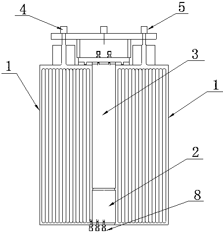
[0046] Such as Figure 1~9 As shown, a non-catalytic reforming reactor includes a heat exchange zone 1, a mixing zone 2, and a reforming reaction zone 3, and is characterized in that: the heat exchanging zone 1 is in the outer layer, and the inner layer is a mixing zone 2 and a reforming reaction zone 3; the mixing zone 2 is located below the reforming reaction zone 3;

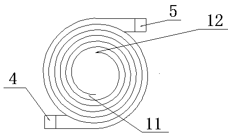
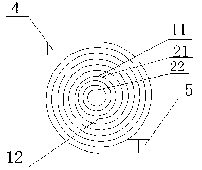
[0047] Heat exchange zone 1 is constructed layer by layer into an end-to-end Swiss roll structure through direct metal laser sintering technology; heat exchange zone 1 realizes heat exchange through the opposite flow of air and product; mixing zone 2 is a detachable spiral tube road 7 structure;

[0048] The reforming reaction zone 3 has a cylindrical structure and is located above the mixing zone 2;

[0049] The air outlet 11 of the heat exchange zone 1 is connected with the air inlet 6 of the mixing zone; the outlet 10 of the mixing zone is connected with the inlet of the reforming reaction zone 3; the out...


PUM


Abstract

The invention discloses a non-catalytic reforming reactor and a technology thereof. The reactor comprises a heat exchange area, a mixing area and a reforming reaction area. The heat exchange area is in an outer layer, and an inner layer is the mixing area and the reforming reaction area. The mixing area is positioned below the reforming reaction area. The heat exchange area is constructed as an end-to-end Swiss-roll-type structure layer by layer through a direct metal laser sintering technology. The heat exchange area is capable of, through air, realizing heat exchange with opposite-type flowof a product. The mixing area is a detachable screw-type pipeline structure. The reforming reaction area is a cylinder structure, and positioned above the mixing area. An air outlet of the heat exchange area is communicated with an air inlet of the mixing area. An outlet of the mixing area is communicated with an inlet of the reforming reaction area. An outlet of the reforming reaction area is communicated with a product inlet of the heat exchange area. The reactor avoids using a catalyst. An inlet reactant of the heat exchange area is the air, so low-energy efficient output is realized. The reactor is capable of improving a reforming productive rate as well as responding to the call of green chemistry.

Description

technical field [0001] The invention relates to a non-catalytic reforming reactor and its technology, in particular to the reforming of methane-rich gas produced by hydrocarbon gas liquid fuel, common biomass pyrolysis gas, coking plant, chemical fertilizer plant, oil refining and coal mining, etc. whole device. Background technique [0002] Partial oxidation is an easy way to convert high energy density hydrocarbon fuels (propane, natural gas, gasoline, JP-8, etc.) into syngas, which can easily be used by solid oxide fuel cells (SOFC) to generate electricity, or Further purification is used for high purity hydrogen generation. Since the partial oxidation reformate retains most of the chemical energy, there are some problems in how to utilize this chemical energy. [0003] Catalytic methods have several disadvantages for reforming hydrocarbon fuels. Catalysts also face challenges when fuels contain high concentrations of sulfur species. Sulfur can poison many catalysts, ...

Claims


Application Information

Patent Timeline
05 Apr 2019
Publication
CN109569490A
IPC
B01J19/24; B01J4/00; B01J19/00; C01B3/36
CPC
B01J4/002; B01J4/008; B01J19/0006; B01J19/0013; B01J19/0053; B01J19/006; B01J19/243; B01J2204/002
Inventors
张国杰; 阎煌煜