Separation system of saturated hydrocarbon cracking gas and utilization method of rich ethane/propane saturated hydrocarbon

A separation system and hydrocarbon cracking technology, applied in the field of saturated resource utilization in refineries, can solve the problems of low investment recovery rate, waste, and high energy consumption

Active Publication Date: 2019-04-26
CHINA PETROLEUM & CHEM CORP +1
View PDF6 Cites 23 Cited by
  • Summary
  • Abstract
  • Description
  • Claims
  • Application Information

AI Technical Summary

Problems solved by technology

At present, the C2C3 concentrated gas recovered from the tail gas of the refinery is mainly sent to different sections of the ethylene plant to increase the production of ethylene propylene. However, for refineries without ethylene production facilities nearby, the concentrated gas The whereabouts is a major pro

Method used


Image

  • Separation system of saturated hydrocarbon cracking gas and utilization method of rich ethane/propane saturated hydrocarbon
  • Separation system of saturated hydrocarbon cracking gas and utilization method of rich ethane/propane saturated hydrocarbon

Examples


Embodiment 1

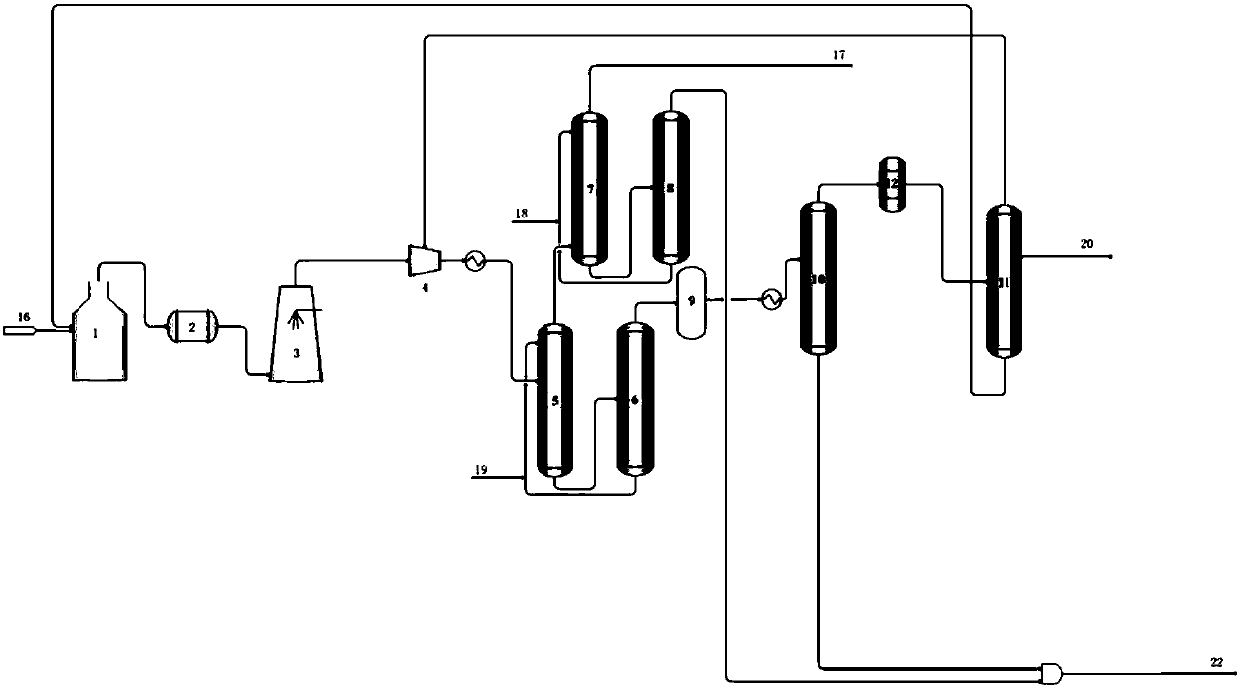
[0069] use as figure 1 A saturated hydrocarbon cracking gas separation system shown includes: cracking furnace 1, waste heat boiler 2, quenching water tower 3, compressor 4, absorption tower 5, desorption tower 6, reabsorption tower 7, gasoline stabilization tower 8, drying tower 9. Deethanizer 10, ethylene rectification tower 11, C2 hydrogenation reactor 12.

[0070] The pyrolysis furnace 1 is connected to the waste heat boiler 2, the quenching water tower 3, and the compressor 4 successively to the middle part of the absorption tower 5, the top of the absorption tower 5 is connected to the reabsorption tower 7, and the tower kettle is connected to the desorption tower 6; The kettle is connected to the gasoline stabilization tower 8, the top of the gasoline stabilization tower 8 is connected to the liquefied gas production line, and the tower kettle is connected to the top of the reabsorption tower 7; the top of the desorption tower 6 is connected to the drying tower 9 and t...

Embodiment 2

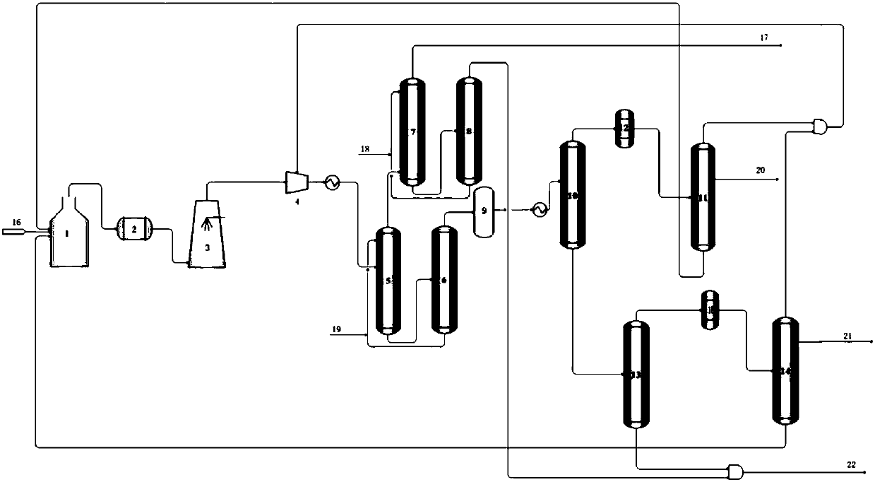
[0089] use as figure 2 A saturated hydrocarbon cracking gas separation system shown includes: cracking furnace 1, waste heat boiler 2, quenching water tower 3, compressor 4, absorption tower 5, desorption tower 6, reabsorption tower 7, gasoline stabilization tower 8, drying tower 9. Deethanizer 10, ethylene rectification tower 11, C2 hydrogenation reactor 12, depropanizer 13, propylene rectification tower 14, C3 hydrogenation reactor 15.

[0090]The pyrolysis furnace 1 is connected to the waste heat boiler 2, the quenching water tower 3, and the compressor 4 successively to the middle part of the absorption tower 5, the top of the absorption tower 5 is connected to the reabsorption tower 7, and the tower kettle is connected to the desorption tower 6; The kettle is connected to the gasoline stabilization tower 8, the top of the gasoline stabilization tower 8 is connected to the liquefied gas production line, and the tower kettle is connected to the top of the reabsorption tower...


PUM


Abstract

The invention belongs to the field of refinery saturated resource utilization, and relates to a separation system of saturated hydrocarbon cracking gas and a utilization method of rich ethane/a propane saturated hydrocarbon. The separation system of the saturated hydrocarbon cracking gas includes a cracking furnace, a waste heat boiler, a quenching water tower, a compressor, an absorption tower, adesorption tower, a reabsorption tower, a drying tower, a deethanization tower, a carbazide hydrogenation reactor and an ethylene rectifying tower, wherein the cracking furnace is connected successively with the waste heat boiler, the quenching water tower and the compressor and then connected with the absorption tower, the tower top of the absorption tower is connected with the reabsorption tower, and the tower kettle of the absorption tower is connected with the desorption tower; the tower top of the desorption tower is connected with the drying tower and then connected with the deethanization tower, and the tower kettle of the desorption tower is connected with the top of the absorption tower; the tower top of the deethanization tower is connected successively with the carbazide hydrogenation reactor and the ethylene rectifying tower; and the tower top of the ethylene rectifying tower is connected with the compressor, the tower kettle of the ethylene rectifying tower is connected with the cracking furnace, and the side part of the ethylene rectifying tower is connected with the production line of polymer grade ethylene products. According to the separation system of the saturated hydrocarbon cracking gas and the utilization method of the rich ethane/the propane saturated hydrocarbon, investment is low, energy consumption is low, the process is simple, and the investment recovery rate is high.

Description

technical field [0001] The invention belongs to the field of utilization of saturated resources in refineries, and more specifically relates to a saturated hydrocarbon cracking gas separation system and a method for utilizing saturated hydrocarbons rich in ethane / propane. Background technique [0002] Ethylene and propylene are important basic chemical raw materials. In the industrial production process, ethylene and propylene are mainly produced by steam cracking (ie thermal cracking) process. In the steam cracking production device, after the cracking raw materials such as light hydrocarbons, naphtha, hydrogenated tail oil, light diesel oil are mixed with water vapor, a thermal cracking reaction occurs in the cracking furnace to generate hydrogen, methane, C2, C3, C4, C5, pyrolysis gasoline, pyrolysis fuel oil and coke and other pyrolysis products. The pyrolysis products are separated and purified in the subsequent separation system to obtain fractions with different carb...

Claims


Application Information

Patent Timeline
IPC IPC(8): C07C5/327C07C7/00C07C7/04C07C7/11C07C7/163C07C7/167C07C11/04C07C11/06
CPCC07C5/327C07C7/005C07C7/04C07C7/11C07C7/163C07C7/167C07C11/04C07C11/06Y02P30/40
Inventor 罗淑娟李东风李琰廖丽华田峻李春芳
Owner CHINA PETROLEUM & CHEM CORP
Why Eureka
Try Eureka