Liquid phase hydrogenation system and method

A liquid-phase hydrogenation and hydrogenation reaction technology, which is applied in the fields of hydrotreating process, petroleum industry, processing of hydrocarbon oil, etc., can solve the problems of long gas-liquid movement path, inability to achieve hydrogenation effect, and difficult operation.

Active Publication Date: 2019-04-26
CHINA PETROLEUM & CHEM CORP +1
View PDF12 Cites 15 Cited by
  • Summary
  • Abstract
  • Description
  • Claims
  • Application Information

AI Technical Summary

Problems solved by technology

In the prior art, the liquid phase hydrogenation reactor with aspect ratio is generally 2.5 to 12. If this reactor uses a conventional gas-liquid mixer and a conventional liquid phase hydrogenation reactor for hydrogenation reaction, there are the following problems: ( 1) The state of hydrogen dissolved and dispersed in the raw oil is unstable. During the hydrogenation reaction process, due to the large height-to-diameter ratio of the reactor and the long gas-liquid movement path, hydrogen is easy to diffuse upward and escape to the top of the reactor. On the one hand, it reduces The efficiency of the hydrogenation reaction is reduced, and the ideal hydrogenation effect cannot be achieved. On the other hand, a large amount of hydrogen is wasted; (2) During the hydrogenation reaction, the by-product H 2 S and NH 3 These substances will inhibit the hydrogenation reaction, especially the deep hydrodesulfurization or denitrogenation reaction, while the material of the conventional liquid phase hydrogenation reactor is operated from top to bottom, so H 2 S and NH 3 Such substances diffuse upward and cannot be removed in time, thus having an adverse effect on the realization of deep hydrogenation
In this method, on the one hand, the combined use of reaction system, circulation system and heating furnace system makes the reaction process very complicated, high cost and difficult to operate; on the other hand, a large amount of circulating materials are introduced, which increases the total volume of the reactor; in addition, The method of dissolving hydrogen for many times still has the problem of upward diffusion of hydrogen, which makes hydrogen diffuse to the top of the reactor and reduces the utilization rate of hydrogen

Method used


Image

  • Liquid phase hydrogenation system and method
  • Liquid phase hydrogenation system and method
  • Liquid phase hydrogenation system and method

Examples


Embodiment 1

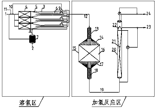
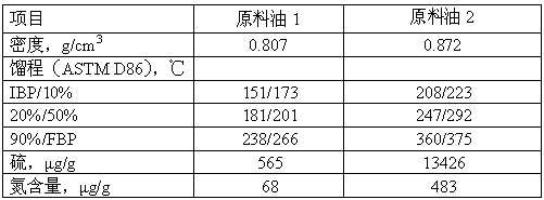
[0052] Using the hydrogen dissolving equipment in the present invention and the conventional liquid-phase hydrogenation reactor, first, the raw material oil 1 and hydrogen are used to form a stable "gas-in-oil" mixed fluid using the hydrogen dissolving equipment in the present invention, and the fluid is introduced into the liquid phase The liquid phase hydrogenation reaction takes place in the phase hydrogenation reactor. The preliminary hydrogen dissolving section in the hydrogen dissolving equipment adopts a cylindrical internal filling porous plate spoiler assembly, the residence time is 2.0 minutes, and the hydrogen escaped at low pressure is recycled, and the flow rate is 0.015% of the raw material mass; the shrinkage of the hydrogen dissolving section is accelerated The angle is 20°, the length ratio of the accelerated hydrogen dissolution section to the hydrogen release section is 1:15; the operating conditions for the introduction position of the hydrogen-rich gas-liqu...

Embodiment 2

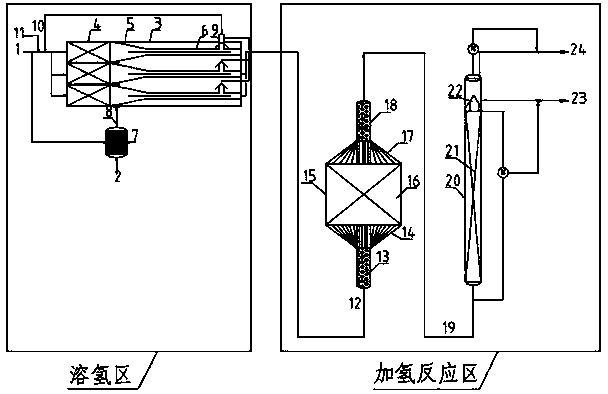
[0054] Adopt conventional static mixer and the present invention figure 1 In the liquid phase hydrogenation reactor, the model of the static mixer is SX2.3 / 25-6.4-500, and the liquid phase hydrogenation reactor contains a fixed bed reactor and a tubular reactor, in which the fixed bed The height-to-diameter ratio of the feed section of the reactor is 10:1, the diameter ratio of the feed section to the hydrogenation reaction section is 1:30, the height-to-diameter ratio of the hydrogenation reaction section is 1:5, and the height-to-diameter ratio of the tubular reactor is 20:1. The diameter ratio of the hydrogenation reaction section in the fixed bed reactor to the tubular reactor is 10:1. The feed section and discharge section of the fixed bed reactor are filled with protective agent FBN-03B01, and the hydrogenation reaction section is filled with hydrogenation catalyst FH-40A; the lower part and the upper part of the tubular reactor are filled separately according to the he...

Embodiment 3

[0056] In the method of the present invention, the attached figure 1 In the hydrogen dissolving and liquid phase hydrogenation reactors shown, the hydrogen dissolving equipment is the same as in Example 1, and the hydrogenation reactor is the same as in Example 2. The raw material oil 1 is used for the hydrogenation reaction, the reaction conditions are shown in Table 2, and the product properties are shown in Table 3.


PUM


Abstract

The invention discloses a liquid phase hydrogenation system and method. The liquid phase hydrogenation system comprises a hydrogen dissolving area and a hydrogenation reaction area; the hydrogen dissolving area is internally provided with a plurality of hydrogen dissolving devices which comprise hydrogen dissolving device shells; a plurality of hydrogen dissolving assemblies which are connected inparallel are included in the hydrogen dissolving device shells; and the hydrogenation reaction area comprises a fixed bed reactor and one or more up-flow-type tubular reactors, wherein the fixed bedreactor and the one or more up-flow-type tubular reactors are connected in series. Fresh raw oil and hydrogen form a 'gas-in-oil' type gas-liquid mixed fluid with the stable state in the hydrogen dissolving area firstly and then enter the hydrogenation reaction area to generate a liquid phase hydrogenation reaction; and according to the method, the 'gas-in-oil' type gas-liquid mixed fluid formed in the hydrogen dissolving area is adopted as a fed material of the liquid phase hydrogenation reaction, the supplementary hydrogen-to-oil ratio in the hydrogenation reaction process can be greatly decreased, the hydrogenation reaction speed is increased, the hydrogenation reaction efficiency is improved, the hydrogen utilization rate is increased, hydrogen consumption and energy consumption are lowered, and deep hydrogenation is achieved.

Description

technical field [0001] The invention belongs to the field of petrochemical industry, and specifically relates to a liquid-phase hydrogenation system and a liquid-phase hydrogenation method. Background technique [0002] Liquid phase hydrogenation technology is a new type of hydrogenation technology. Compared with the conventional trickle bed gas\liquid\solid three-phase hydrogenation process, it has the advantages of simple process flow, saving investment, reducing production costs, and high reaction efficiency. In the conventional trickle bed hydrogenation reaction process, hydrogen is mainly used for mass transfer, that is, the speed at which hydrogen diffuses from the gas phase and dissolves into oil is the rate-controlling step of the entire hydrogenation reaction. The liquid-phase hydrogenation process eliminates the influence of hydrogen diffusion and mass transfer, so that the hydrogenation reaction is carried out in the kinetic control zone, that is, the hydrogen is ...

Claims


Application Information

Patent Timeline
Patent Type & Authority Applications(China)
IPC IPC(8): C10G65/02
CPCC10G65/02
Inventor 李明林杨秀娜金平王昊辰齐慧敏
Owner CHINA PETROLEUM & CHEM CORP
Why Eureka
Try Eureka