
Sleeve Type Ultra-thin Bone Fixation Pin

A fixation needle and cannula-type technology, which is applied in the direction of fixators, internal fixators, and internal bone synthesis, can solve the problems of limited wide application, large surgical trauma, and iatrogenic fractures, and achieve strong operability and adaptability. Widespread effect

Active Publication Date: 2020-08-11
王力平
View PDF10 Cites 0 Cited by
  • Summary
  • Abstract
  • Description
  • Claims
  • Application Information

AI Technical Summary

Problems solved by technology

However, the current reality faced by the laboratory is that the toughness of the tibia means that smaller needles (eg, 30G gauge, 0.30mm diameter) may bend or become weak when drilling into bone tissue and fail to penetrate the bone.
Therefore, we have to risk iatrogenic fractures that may be caused by small tibial bone punctures, and are forced to use larger and stronger bone puncture needles; Can replace a new puncture needle and continue to drill, and often need several needles in succession to complete the drilling and puncture; this method can only be operated on young animals whose bone tissue is not very tough
In addition, because the puncture needle is too thin, it can only be carefully drilled into the bone by hand, and cannot be driven by a motor.
Repeating the time-consuming manual drilling of multiple needles increases the risk of surgical trauma and infection; this method is very prone to needle failure, iatrogenic fractures, or loosening of implanted needles; finally, this operation requires well-trained Highly skilled professionals often need to invest a lot of training and learning time, which greatly increases the overall cost of animal experiments
[0006] Similarly, in the fixation surgery for tension band and stress bone fracture reduction and bone defect repair in the hands, feet, wrists, ankles and other parts of clinical medicine, because the bones in these positions are small and the tendon nerves are densely distributed, traditional steel plates and The screw internal fixation technique has a large surgical trauma, and the stability of small bone blocks or bone fragments is poor for a certain period of time. The probability of local nerve and extensor tendon damage during fixation is high; it affects the effect of surgical fixation, and the time for functional exercise is delayed, especially after bone healing. Need to perform another skin-opening and invasive surgery to remove the metal fixture
These deficiencies have led to more stringent, time-consuming and expensive professional technical requirements for hand, ankle, wrist and ankle trauma repair.
However, there are two obvious complications with the use of Kirschner wires, namely, the protruding ends of the Kirschner wires irritate the surrounding soft tissue and the displacement of the Kirschner wires.
In addition, in actual operation and application, the minimum diameter of the electric drill that can penetrate into the bone Kirschner wire is 0.8mm. If the diameter is too small, the needle body will be too thin to be held by electric tools, or the needle body will be too soft and easy to bend and cannot be powered. drill into bone
Therefore, the traditional Kirschner wire anchor fixation method, the soft tissue irritation caused by the protruding tail end and the disadvantages of easy slippage caused by needle withdrawal limit the wide application of Kirschner wire technology in the field of clinical bone fixation.

Method used


Image

  • Sleeve Type Ultra-thin Bone Fixation Pin
  • Sleeve Type Ultra-thin Bone Fixation Pin
  • Sleeve Type Ultra-thin Bone Fixation Pin

Examples


Embodiment 1

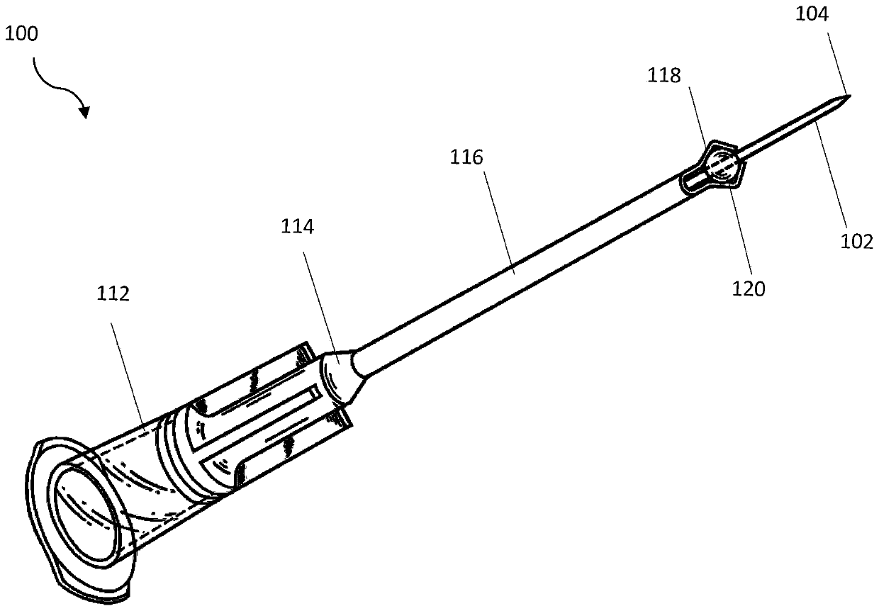
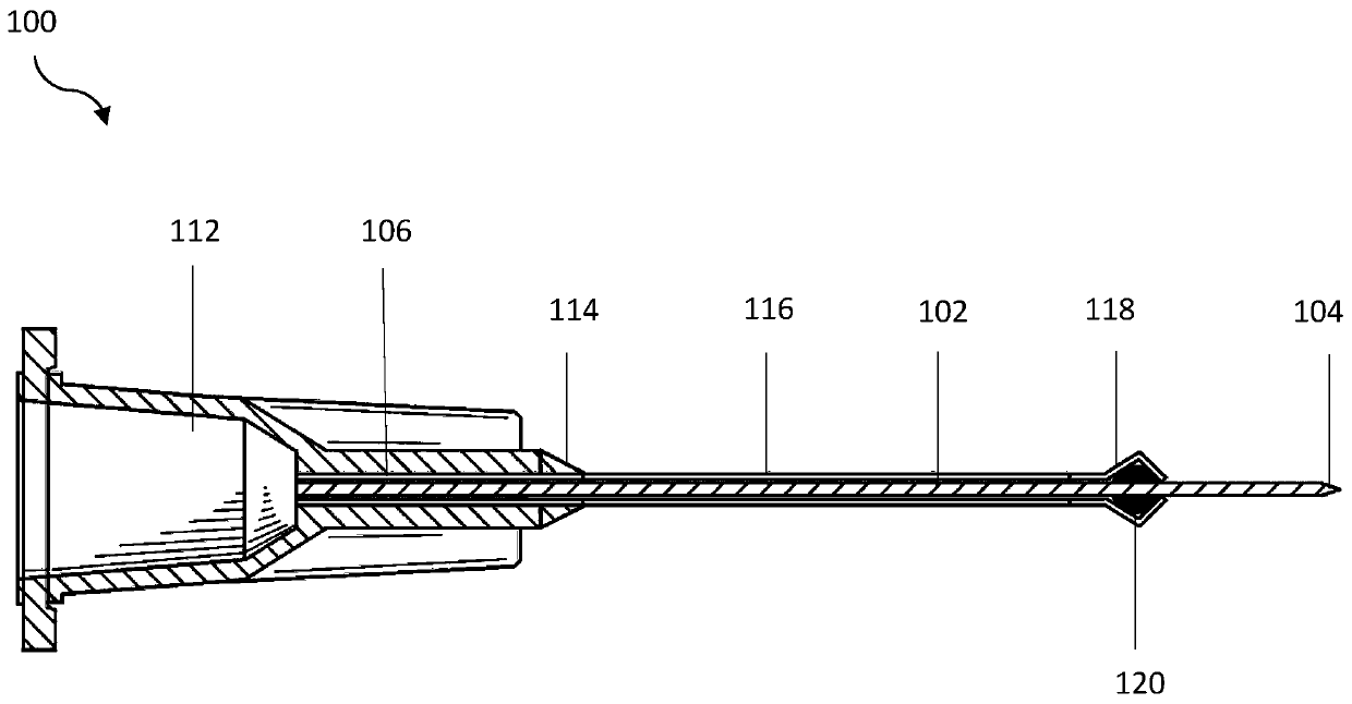
[0083] Such as Figure 1-7D The illustrated sleeve-type ultra-thin bone fixation pin 100 includes a booster sleeve 116 and an ultra-thin bone fixation pin 102 built in the booster sleeve. The bone fixation pin 102 is 0.3mm in diameter.

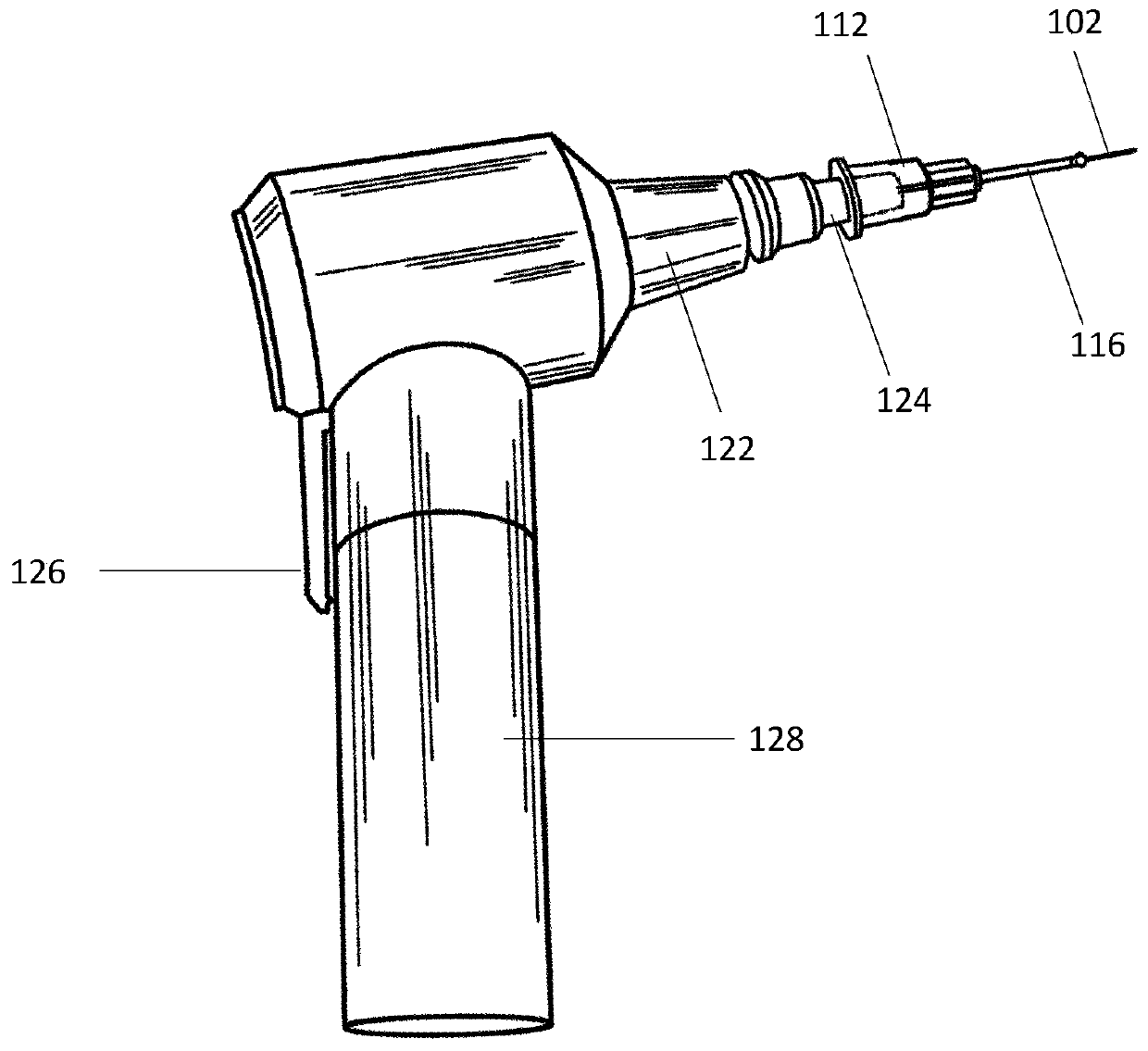
[0084] One end of the booster sleeve 116 is provided with an adapter seat 112 connected with the rotor adapter head 124 of the drive motor 122 . The bone fixation pin 102 is loaded in the booster sleeve 116, and is rigidly connected by the clamping arm 118 at the distal end of the booster sleeve 116 and the detachable rigid plastic ball 120; the clamping arm 118 and the detachable rigid plastic ball 120 bind the bone The fixation needle 102 and the booster sleeve 116 are rigidly integrated, and the length of the pin tip of the bone fixation pin 102 extending out of the booster sleeve 116 is locked to 6 mm, so as to ensure that the protruding needle tip has sufficient mechanical strength to meet the requirements of percutaneous electrokinetics...

Embodiment 2

[0093] Such as Figure 8-1 The type II cannula type ultra-thin bone fixation needle shown in 0 includes a type II needle sleeve 214 and a built-in type II needle 202 . Type II needle 202 has a diameter of 0.5 mm.

[0094] Such as Figure 8 , 9A , 9B, one end of the type II needle sleeve 214 is provided with a type II needle adapter seat 212 connected to the rotor of the drive motor, the type II needle adapter seat is in the shape of a hexagonal prism, and is compatible with the type II needle adapter cavity 210 of the cordless motor match. The type II needle 202 is loaded in the type II needle cannula 214, and is rigidly connected by the cannula tightening thread 216 at the distal end of the type II needle cannula 214 and the cannula tightening nut 218.

[0095] Such as Figure 10A , 10B As shown in , 10C and 10D, the distal port of the type II needle cannula 214 is divided into three equal parts, and extended as trapezoidal flaps, and the casing tightening threads 216 a...

Embodiment 3

[0097] This example is used to explain the application method and process of the cannula-type ultra-thin bone fixation needle of the present invention in external fixation of mouse tibia.

[0098] Such as Figure 11-30 Shown is a schematic diagram of establishing a mouse tibia-femoral external fixator model using the sleeve type ultra-fine bone fixation needle of the present invention.

[0099] Such as Figure 11 As shown, the mouse is fixed in the orthopedic surgery fixation device 300, the hind limb of the mouse is placed in a standard position in front of the animal orthopedic surgery positioning fixture 302, and a positioning needle hole 304 that can be positioned through the anatomical position popliteal fossa is shown.

[0100] Such as Figure 12 As shown, the mouse hindlimb is positioned on the animal bone surgical fixation device, and is positioned through the anatomical position of the popliteal fossa by a 25G syringe needle as a positioning pin 306 passing through ...


PUM


Abstract

A sleeve-type superfine diameter osteofixation needle (100), comprising a power assisting sleeve (116, 214) and a superfine diameter osteofixation needle (102, 202) disposed in the power assisting sleeve (116, 214), one end of the power assisting sleeve (116, 214) being provided with an adapter seat (112, 212) to connect to a rotor of a drive electric motor (122), and another end being provided with a detachable rigid connection apparatus, the power assisting sleeve (116, 214) being fixed to the osteofixation needle (102, 202) by means of the rigid connection apparatus, and the rigid connection apparatus limiting extension of a needle tip (104) of the osteofixation needle (102, 202) from the power assisting sleeve (116, 214) to a set length. Starting the electric motor (122) can cause the electrically driven osteofixation needle (100) to enter a bone by means of percutaneous self-tapping drilling, and after the needle tip (104) of the osteofixation needle (102, 202) extending from the power assistance sleeve (116, 214) penetrates a target bone, detaching the rigid connection apparatus from a distal end of the power assistance sleeve (116, 214), removing the power assistance sleeve (116, 214) from the osteofixation needle (102, 202); finally, screwing into an anchor bone matrix by means of needle-holding forceps gripping a screw thread section (106) of a back part of the osteofixation needle (102, 202). Feasibility of percutaneous anchor needle puncturing is realized for small animal bone fracture and bone malformation models and clinical osteofixation of small bone breaks in specific parts, including hand and foot; the method is simple and convenient, time-saving and efficient, causes little surgical trauma, and needle anchoring stability is reliable.

Description

technical field [0001] The invention relates to a medical device, specifically for the establishment of experimental animal fracture and segmental bone defect models, as well as for the purpose of medical repair of fracture bone defects in specific parts such as hands and feet in clinical medicine. And clinical hands, feet, wrists, ankles and other small bones and multi-joint tendons and nerve-intensive parts of the bone environment to implement bone fixation special surgical instruments. Background technique [0002] External fixation techniques for fractures and bone defects are widely used in orthopedics and bone trauma repair operations. However, laboratory small animal orthopedic procedures, such as tibial external fixation of the lower leg in mice, are limited by the lack of bone fixation instruments suitable for use in the small tibial environment in the study of bone-based disciplines in human life sciences. This directly makes it difficult for researchers to use ex...

Claims


Application Information

Patent Timeline
Patent Type & Authority Patents(China)
IPC IPC(8): A61B17/68A61D1/00
CPCA61D1/00A61B17/16
Inventor 王力平
Owner 王力平
Learn More