

An Impedance Adaptive Laser Diode Driver
A laser diode, adaptive technology, used in lasers, laser parts, semiconductor lasers, etc., can solve the problems of laser diode damage, no over-current power-off and over-temperature power-off protection functions
- Summary
- Abstract
- Description
- Claims
- Application Information
AI Technical Summary
Problems solved by technology
Method used
Image

Examples
Embodiment 1
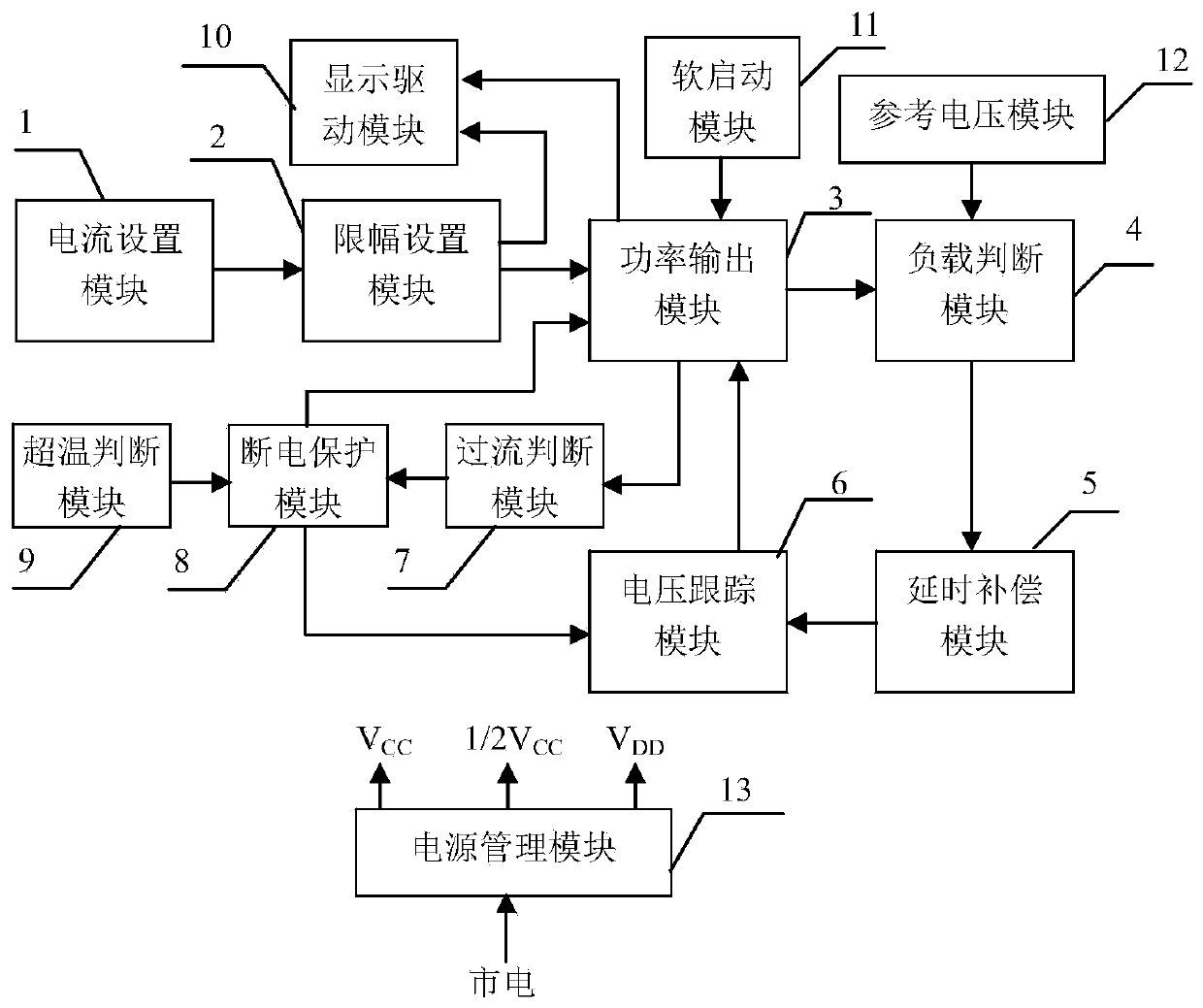
[0046] Embodiment 1 Overall structure of the present invention
[0047] Overall structure of the present invention is as figure 1As shown, there are current setting module 1, limiting setting module 2, power output module 3, load judging module 4, delay compensation module 5, voltage tracking module 6, overcurrent judging module 7, power-off protection module 8, over-temperature Judgment module 9, display drive module 10, soft start module 11, reference voltage module 12, power management module 13 and front panel 14; Wherein, current setting module 1 is connected with limiting setting module 2, and limiting setting module 2 is also connected with respectively The power output module 3 is connected to the display driver module 10, the soft start module 11 is connected to the power output module 3, the power output module 3 is respectively connected to the display driver module 10, the load judgment module 4, and the overcurrent judgment module 7, and the reference voltage modu...
Embodiment 2
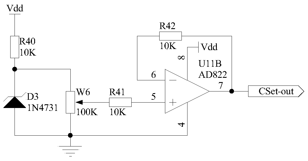
[0048] Embodiment 2 The current setting module of the present invention
[0049] The current setting module 1 of the present invention can adopt such as image 3 In the structure shown, one end of the resistor R40 is connected to the power supply Vdd, the other end is connected to the cathode of the Zener diode D3 and a fixed end of the sliding rheostat W6, the anode of the Zener diode D3 is grounded, the other fixed end of the sliding rheostat W6 is grounded, and the resistor One end of R41 is connected to the sliding wire end of the sliding rheostat W6, the other end is connected to the non-inverting input end of the operational amplifier U11B, the inverting input end of the operational amplifier U11B is connected to one end of the resistor R42, and the other end of the resistor R42 is connected to the output end of the operational amplifier U11B. And as the output terminal of the current setting module 1, denoted as port CSet-out, connected to the input terminal of the limi...
Embodiment 3
[0051] Embodiment 3 Limit setting module of the present invention
[0052] The principle circuit of limiter setting module 2 of the present invention is as Figure 4 As shown, one end of the resistor R45 is used as the input end of the limit setting module 2, which is denoted as port CL-in, and is connected to the output end of the current setting module 1 (that is, the port CSet in Embodiment 1), and the other end is connected to the operational amplifier U12B The non-inverting input terminal of the diode D4 and the positive pole of the diode D4, the negative pole of the diode D4 is connected to the output terminal of the operational amplifier U11A and one end of the resistor R44, the other end of the resistor R44 is connected to the inverting input terminal of the operational amplifier U11A, and the non-inverting input terminal of the operational amplifier U11A is connected to the One end of the resistor R43 is connected, the other end of the resistor R43 is connected to the...
PUM
 Abstract
Description
Claims
Application Information