
A method of creating a multi-image-based multifunctional embedded system

An embedded system, multi-functional technology, applied in response to error generation, program control device, boot program, etc., can solve problems such as damage to system deployment flexibility, data leakage, operating system data damage, etc., to increase predictability and real-time, prevent unauthorized access, save storage memory effect

Active Publication Date: 2019-05-21
潘润宇
View PDF3 Cites 1 Cited by
  • Summary
  • Abstract
  • Description
  • Claims
  • Application Information

AI Technical Summary

Problems solved by technology

[0004] (1) Lack of isolation between kernel mode and user mode, the operating system and application program run in the same address space, once the application program crashes, the data of the operating system may also be destroyed
[0005] (2) There is a lack of isolation between various applications. Once one of the applications fails, the reliability of the entire system will be destroyed.
[0006] (3) The information security of the application program is poor. Once any component is compromised, it may lead to data leakage of the entire system
[0007] (4) Application deployment is cumbersome. In traditional embedded systems, the entire system needs to be compiled into a single image, which damages the flexibility of system deployment and increases the burden of image assembly for users
[0008] (5) The memory organization of the application program is cumbersome. In a small number of applications that support kernel mode user mode and address space isolation between applications, the system designer needs to clearly specify the settings of each protection domain for each application. Due to the support of each hardware The number and limit of protection domains are different. When the number of protection domains used by the application is greater than that provided by the hardware, in order to reduce the number of protection domains, it is necessary to manually adjust the memory layout of the application to merge some protection domains.
[0009] (6) It is difficult to perform dynamic memory allocation. Once dynamic memory allocation is performed, a new protection domain may be required. When the protection domain provided by the hardware is exhausted, the new memory cannot be accessed by applications
[0010] (7) The system may have a variety of memories with different access delay or bandwidth or persistence properties. It is difficult for the interface of the existing operating system to specify the properties of the allocated memory. For example, an embedded system may have SRAM, DRAM and FRAM at the same time The memory of the three attributes, and the application wants to specify the allocation of storage space on one of the memories

Method used


Image

  • A method of creating a multi-image-based multifunctional embedded system
  • A method of creating a multi-image-based multifunctional embedded system
  • A method of creating a multi-image-based multifunctional embedded system

Examples


Embodiment 1

[0080] Example 1; see Figure 14A and Figure 14B Shown:

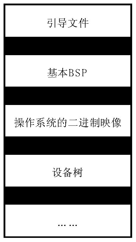
[0081] refer to figure 1 , figure 2 and image 3 As shown, the embedded system 100 includes an operating system module image 110 and two application program module images 120 and 130 , both of which are stored in the system memory 140 .

[0082] The embedded system 100 uses a memory protection unit 150 to implement hardware memory protection, and the memory protection unit has two protected area register groups 151 and 152 .

[0083] refer to Figure 5 As shown, the application program module 120 includes two non-real-time memory segments 121 and 122 , and the application program module 130 includes a real-time memory segment 131 and two non-real-time memory segments 132 and 133 .

[0084] Step 500: the embedded system starts and reads the operating system module image 110 from the system memory 140, forms the operating system module 160 in the memory, and jumps to its entry point to start execution;

[0085] S...

Embodiment 2

[0099] Example 2; see Figure 15A and Figure 15B Shown:

[0100] refer to figure 1 , figure 2 and image 3 As shown, the embedded system 200 does not contain any image, and its system memory 210 is empty or only has a basic file system 220 .

[0101] There is a network port 230 on the motherboard of the embedded system 200 , and images can be downloaded through the network port 230 .

[0102] Hardware memory protection is performed using a base-length based memory management unit 240 with four protected region register sets 241-244.

[0103] refer to Figure 5 As shown, the application program module 250 includes 4 non-real-time memory segments 251-254, and the application program module 260 includes 2 real-time memory segments 261 and 262 and 2 non-real-time memory segments 263 and 264.

[0104] Step 700: The embedded system starts and reads the operating system module image 270 through the network port 230, forms the operating system module 280 in the memory, and ju...

Embodiment 3

[0120] Example 3; see Figure 16A , Figure 16B , Figure 16C , Figure 16D and Figure 16E As shown: the embedded system 900 includes three kinds of system memory: static random access memory 910 , dynamic random access memory 920 and ferroelectric memory 930 .

[0121] The embedded system 900 has completed the power-on and loading work, and has an operating system module 940 and an application program module 950 inside its SRAM. The memory layout of the system is as follows: Figure 16A As shown, system components that are not directly related in the figure have been omitted.

[0122] Step 990: the application module 950 requests to apply for a storage area with low latency and high bandwidth by calling the sys_mem_add interface;

[0123] Step 991: the operating system module 940 checks the authority of the application program module 950, confirms that it has the ability to apply for the memory, and allocates a memory block 960 that is allowed to be accessed by the appl...


PUM


Abstract

The invention discloses a method for creating a multi-image-based multifunctional embedded system, which is characterized in that a memory protection unit and a base address-length type memory management unit which are common on small embedded hardware of a single-chip microprocessor are allowed to be used, and the fact that the number of memory segments of the application program module to exceedthe number of memory segments directly supported by hardware is allowed, if the memory layout of the application program is relatively complex, descriptors of a part of memory segments is loaded intoa hardware register for protection, and the memory layout is stored by using an app _ mem _ trie data structure. The method has the advantages that the flexibility and the safety of the system are improved; Query and modification of deterministic worst execution time are allowed while the storage memory is saved, and the predictability and real-time performance of the system are improved; It is guaranteed to the maximum extent that access of the real-time memory segment does not generate memory access abnormity, the predictability and real-time performance of the system are guaranteed, and high practical value and practical significance are achieved.

Description

technical field [0001] The invention belongs to the technical field of the Internet of Things and embedded systems, and in particular relates to a method for creating a multi-image-based multifunctional embedded system. Background technique [0002] At present, the functions of embedded systems are becoming more and more diversified, the demand for application modular loading is becoming more and more common, and the requirements for safety and reliability are also increasing day by day. The existing multi-functional embedded systems cannot meet the requirements of modular loading of embedded systems and cannot guarantee the safety and reliability of the entire system. [0003] At present, the traditional existing multifunctional embedded systems have the following defects: [0004] (1) There is a lack of isolation between the kernel state and the user state. The operating system and the application program run in the same address space. Once the application program crashes...

Claims


Application Information

Patent Timeline
IPC IPC(8): G06F9/4401G06F9/445G06F12/02G06F11/07
Inventor 潘润宇
Owner 潘润宇
Learn More