Oil displacement method of oil reservoir

An oil displacement method and oil displacement technology, which are applied in chemical instruments and methods, earthwork drilling, production of fluids, etc., can solve the problems such as the recovery factor to be improved, and reduce the viscosity of crude oil, improve the fluidity, and improve the efficiency of oil washing. The effect of sweeping efficiency improvement

Pending Publication Date: 2019-05-28
CHINA PETROLEUM & CHEM CORP +1
View PDF11 Cites 16 Cited by
  • Summary
  • Abstract
  • Description
  • Claims
  • Application Information

AI Technical Summary

Problems solved by technology

[0009] The purpose of the present invention is to overcome the problem that the recovery factor of the prior art needs to be improved, and to provide a method for flooding

Method used


Image

  • Oil displacement method of oil reservoir
  • Oil displacement method of oil reservoir

Examples


Embodiment 1

[0066] This example is used to illustrate the preparation and performance of each slug provided by the present invention.

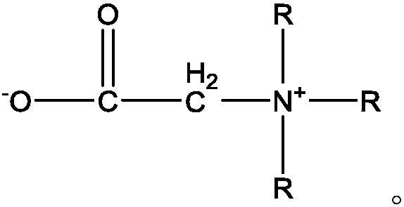
[0067] (1) Pre-slug A: Weigh 800g of clean water (with a salinity of 0mg / L), add polyacrylamide (viscosity average molecular weight 3000×10) under stirring conditions 4 , Degree of hydrolysis 20%) 3g, stirring and dissolving for 4h. Add 3 g of dimethyl dioctadecyl ammonium chloride as a cationic surfactant, add water to 1000 g, and stir for 20-30 minutes until completely dissolved.

[0068] Viscosity-reducing flooding system B: Weigh 800g of clear water (with a salinity of 0mg / L), and add polyacrylamide (viscosity average molecular weight 3000×10) under stirring conditions 4 , Degree of hydrolysis 20%) 3g, stirring and dissolving for 4h. Add 3 g of dimethyl dioctadecyl ammonium chloride, a cationic surfactant, 3 g of octadecyl dimethyl betaine, and 0.5 g of ethanol, add water to 1000 g, and stir for 20-30 minutes until completely dissolved.

[0069] Protection ...

Embodiment 2

[0072] This example is used to illustrate the use effect of the oil displacement method on the enhanced oil recovery of heavy oil.

[0073] A core with a size of 4.5mm×4.5mm×300mm and a permeability of 3000md was used for the enhanced oil recovery experiment (the oil displacement system is the same as in Example 1). The core was dried, evacuated and saturated with water, saturated with heavy oil at 70°C (same as Example 1), and aged for 48h. (1) The injection rate of 1.5 mL / min is water driven to 95% by volume of water. (2) Inject the pre-slug A 0.05PV at 1.5mL / min injection rate, and inject CO at 1.0mL / min injection rate 2 0.05PV; (3) Inject the viscosity-reducing oil displacement system B0.05PV at 1.5mL / min injection rate, and inject CO at 1.0mL / min injection rate 2 0.05PV, repeated alternate injection for 3 cycles. (4) Inject the protective slug C 0.05PV at an injection rate of 1.5 mL / min; (5) Continue the water drive at an injection rate of 1.5 mL / min to 95 vol% water.

[0...

Embodiment 3

[0076] This example is used to illustrate the preparation and performance of each slug provided by the present invention.

[0077] (1) Use high salinity water (salinity 100000mg / L, of which Ca 2+ Concentration: 10000mg / L), pre-slug A, viscosity-reducing oil displacement system B and protective slug C are prepared. The preparation method is the same as in Example 1.

[0078] (2) Take the above-mentioned pre-slug A, viscosity reduction oil displacement system B and heavy oil (50℃ viscosity 9600mPa.s), and use Model TX500C interfacial tension to determine the interfacial tension at 70℃ to be 3.9×10 -4 mN / m and 6.3×10 -3 mN / m. In a 100 mL beaker, respectively take 30 g of the above-mentioned pre-slug A and viscosity-reducing oil displacement system B, add 70 g of heavy oil, and place the beaker in a water bath at 70°C for 2 hours and stir for 3 minutes. Using Brookfield DV-II viscometer at 70℃, the shear rate is 7.34S -1 Under the conditions, the measured viscosity of the mixed soluti...


PUM


Abstract

The invention relates to the field of oil displacement of an oil reservoir and discloses an oil displacement method of an oil reservoir. The oil displacement method comprises the steps of injecting apreposed slug A into an oil layer from an injection well, then injecting gas, sequentially and alternately injecting a viscosity reduction oil displacement system B and the gas, injecting a protectionslug C, and injecting water at last, wherein the preposed slug A is an aqueous solution containing a surfactant and/or a polymer; the viscosity reduction oil displacement system B comprises a surfactant, alcohol, a polymer and water; and the protection slug C is an aqueous solution containing a polymer. According to the method, a shearing effect of an emolsifier and high-viscosity oil in a deep stratum is enhanced by a periodically changed 'liquid-gas' alternating injection method; emulsification of the high-viscosity oil in the deep stratum is promoted; an emulsification and displacement effect of an oil displacement system in the deep stratum is strengthened; and displacement efficiency and sweep efficiency in an oil displacement process are significantly improved.

Description

Technical field [0001] The invention relates to an oil reservoir flooding method, in particular to an oil reservoir flooding method suitable for heavy oil exploitation. Background technique [0002] Heavy oil refers to crude oil with a viscosity greater than 50mPa.s at 50°C. Heavy oil development occupies a certain proportion of my country's oil and gas development. Heavy oil is distributed in Liaohe Oilfield, Shengli Oilfield, Xinjiang Oilfield, Zhongyuan Oilfield and Jiangsu Oilfield. The existing heavy oil development technology is mainly based on thermal oil recovery, which reduces the viscosity of the heavy oil by heating, improves the fluidity of the heavy oil, and increases the recovery rate. The main disadvantage of thermal oil recovery is its high energy consumption. For reservoirs with deep burial, thin oil layers and high water cut, the heat utilization rate is low during thermal recovery. In contrast, the process of "cold production" of heavy oil is not restricted ...

Claims


Application Information

Patent Timeline
IPC IPC(8): E21B43/22C09K8/594C09K8/58
Inventor 江建林纪洪波
Owner CHINA PETROLEUM & CHEM CORP
Why Eureka
Try Eureka