Refinery dry gas separation method and refinery dry gas separation apparatus

A technology of refinery dry gas and separation method, which is applied in the directions of absorption purification/separation, distillation purification/separation, climate sustainability, etc. Ideal effect, lower investment, good selectivity

Active Publication Date: 2019-06-21
CHINA PETROLEUM & CHEM CORP +1
View PDF6 Cites 30 Cited by
  • Summary
  • Abstract
  • Description
  • Claims
  • Application Information

AI Technical Summary

Problems solved by technology

However, this method has a large amount of absorbent circulation and high energy consumption
[0008] In summary, the existing refinery dry g

Method used


Image

  • Refinery dry gas separation method and refinery dry gas separation apparatus
  • Refinery dry gas separation method and refinery dry gas separation apparatus
  • Refinery dry gas separation method and refinery dry gas separation apparatus

Examples


Embodiment 1

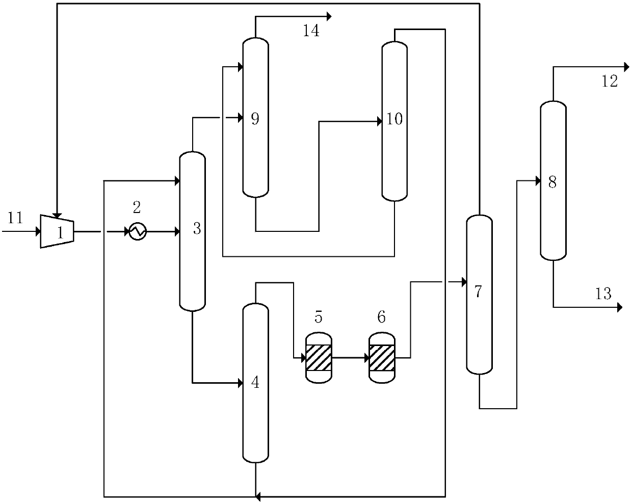
[0058] use as figure 1 Refinery dry gas separation unit shown. Including: a compressor 1, a cooler 2, an absorption tower 3, a desorption tower 4, a purification unit 5, a drying unit 6, a demethanizer 7 and an ethylene rectification tower 8; the top of the absorption tower 3 is connected to a reabsorption tower 9 and Gasoline stabilization tower 10, the bottom of the tower is connected to the desorption tower 4; the top of the desorption tower 4 is connected to the purification unit 5 and the drying unit 6 in turn, and then connected to the demethanizer 7; the top of the demethanizer 7 is connected to the first section of the compressor , the bottom of the tower is connected to the ethylene rectification tower 8; the top of the ethylene rectification tower 8 is connected to the production line of the polymer grade ethylene product, and the bottom of the tower is connected to the production line of the rich ethane product; the bottom of the gasoline stabilization tower 10 is c...

Embodiment 2

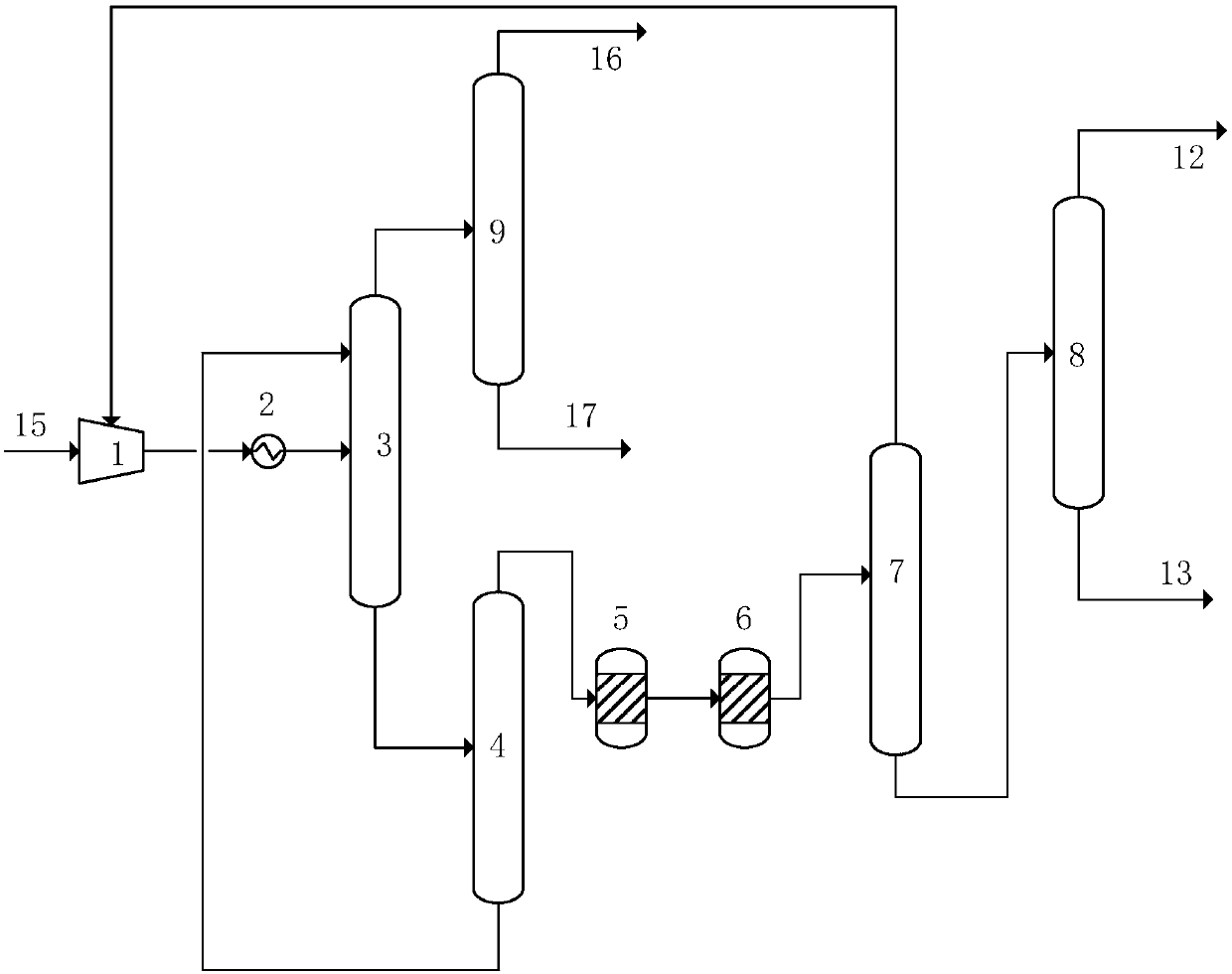
[0078] use as figure 2 In the shown separation device, crude gas 15 (dry gas, see Table 3 for composition) from a factory enters the separation device.

[0079] The separation device comprises: a compressor 1, a cooler 2, an absorption tower 3, a desorption tower 4, a purification unit 5, a drying unit 6, a demethanizer 7 and an ethylene rectification tower 8; Tower 9, the bottom of the tower is connected to the desorption tower 4; the top of the desorption tower 4 is connected to the purification unit 5 and the drying unit 6 in turn, and then connected to the middle part of the demethanizer 7, and the bottom of the tower is connected to the top of the absorption tower 3; the top of the demethanizer 7 The top is connected to the section 1 of the compressor, and the bottom of the tower is connected to the middle part of the ethylene rectification tower 8.

[0080] The separation method includes the following steps:

[0081] (1) Compression: the crude gas 15 from a certain fa...


PUM


Abstract

The invention belongs to the field of chemical industry gas separation, and particularly provides a refinery dry gas separation method and a refinery dry gas separation apparatus. The method comprises: (1) compression: pressurizing refinery dry gas; (2) cooling: cooling the compressed gas, and conveying to an absorption tower; (3) absorption: making the stream on the top of the absorption tower enter a re-absorption unit or be cooled, and conveying the stream on the tower kettle to a desorption tower; (4) desorption: obtaining C2 concentrated gas from the top of the desorption tower, obtaininga lean solvent from the tower kettle, cooling the lean solvent, and returning to the top portion of the absorption tower; (5) purification: purifying the C2 concentrated gas obtained from the top ofthe desorption tower; (6) methane removing: making the purified C2 concentrated gas enter a methane removing tower, wherein the material from the top of the methane removing tower returns to a compressor or is conveyed outside the boundary area, and the material from the tower kettle is conveyed to an ethylene rectification tower; and (7) ethylene rectification: extracting a polymerization-grade ethylene product from the top of the ethylene rectification tower, wherein the material from the tower kettle is an ethane-rich product. According to the present invention, the method and the apparatushave advantages of simple process, high recovery rate, low energy consumption and the like.

Description

technical field [0001] The invention belongs to the field of chemical gas separation, and more specifically relates to a refinery dry gas separation method and a refinery dry gas separation device. Background technique [0002] A large amount of tail gas will be produced in the process of oil refining and chemical production, some of which, such as tail gas produced by catalytic cracking, thermal cracking, delayed coking, hydrocracking and other production processes, contain a lot of carbon 2 and carbon 3 components, especially some tail gas , the ethane content is relatively high. At present, most refineries in my country still burn the refinery dry gas as fuel gas, which has low utilization value and causes great waste of resources and environmental pollution. [0003] If the ethylene and ethane in the refinery dry gas are recovered, ethylene is used as the raw material for polymerization, and the ethane is sent to the ethylene plant as the raw material for ethylene produ...

Claims


Application Information

Patent Timeline
IPC IPC(8): C07C11/04C07C7/11C07C7/04
CPCY02P20/129
Inventor 罗淑娟廖丽华张敬升李东风刘智信过良邵华伟
Owner CHINA PETROLEUM & CHEM CORP
Why Eureka
Try Eureka