
Method and device for deep desulfurization and alkali control of sulfur incineration tail gas by sodium process

A deep desulfurization and tail gas technology, applied in the field of sulfuric acid gas, tail gas sodium method deep desulfurization and alkali control after sulfur incineration, desulfurization separation device, can solve the problem of difficult desulfurization efficiency of the system, incomplete removal of mist eliminators, increased investment costs, etc. problems, to achieve the effect of avoiding white smoke, reducing mist content, and large processing capacity

Pending Publication Date: 2019-07-05
ZHENHAI PETROCHEMICAL ENG CO LTD
View PDF7 Cites 6 Cited by
  • Summary
  • Abstract
  • Description
  • Claims
  • Application Information

AI Technical Summary

Problems solved by technology

Double absorption towers can increase the processing capacity and desulfurization efficiency, but correspondingly, the investment cost will increase accordingly. It is difficult to maintain the desulfurization efficiency of the system in the case of high sulfur content in the sulfuric acid gas generated in the refining process
A demister is used at the top of the tower to remove the mist entrained in the gas, but the demister is not completely removed, and there are still droplets, resulting in gas pollution and loss of lye

Method used


Image

  • Method and device for deep desulfurization and alkali control of sulfur incineration tail gas by sodium process
  • Method and device for deep desulfurization and alkali control of sulfur incineration tail gas by sodium process
  • Method and device for deep desulfurization and alkali control of sulfur incineration tail gas by sodium process

Examples


Embodiment 1

[0107]In the flue gas desulfurization device in the sulfur recovery unit of a 40 million tons / year refining and chemical integration project phase I project of Zhejiang Petrochemical Co., Ltd., according to the method of the present invention, the sodium method wet desulfurization and alkali control method is adopted, Filter and purify the flue gas containing solid particles and sulfur dioxide, and remove the particles and sulfur components. The specific operation process and effect are described as follows:

[0108] 1. Material properties and related parameters

[0109] The temperature of the tail gas after incineration in the sulfur plant is 260°C, and the density is 0.6523kg / m 3 , the flue gas volume is 16091-122700Nm 3 / h, the sulfur dioxide content is 560mg / Nm 3 (approximately 200ppm), the feed water is fresh water from the sulfur plant, the temperature is 40°C, and the pressure is 0.4MPa. The lye is sodium hydroxide solution, the concentration of lye is 30%wt, the nor...


PUM


Abstract

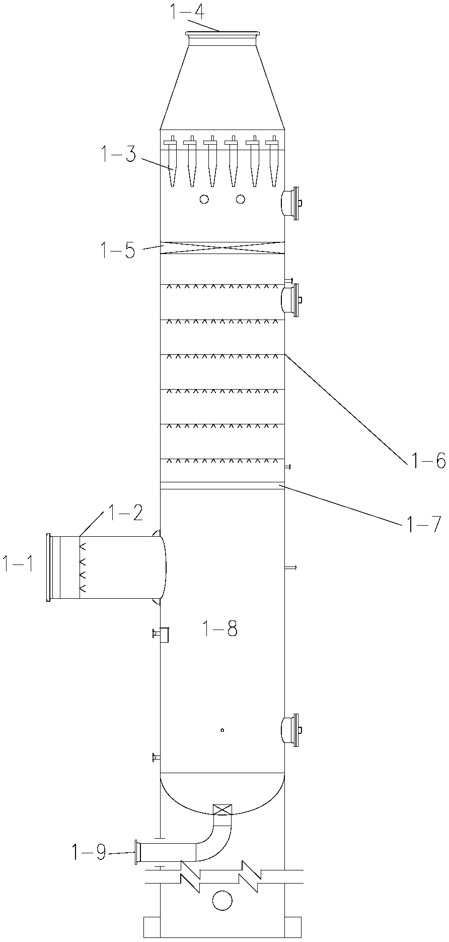
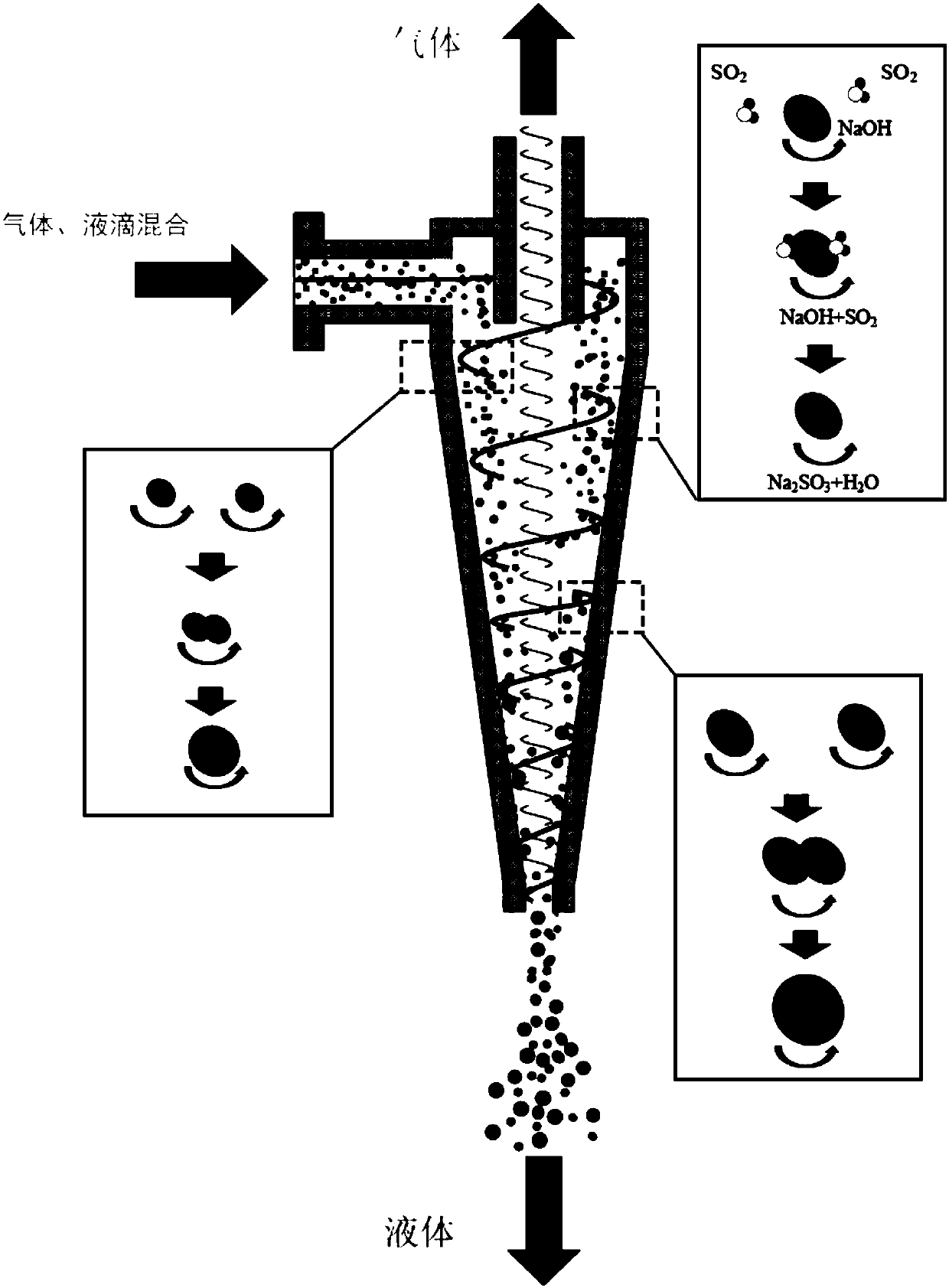
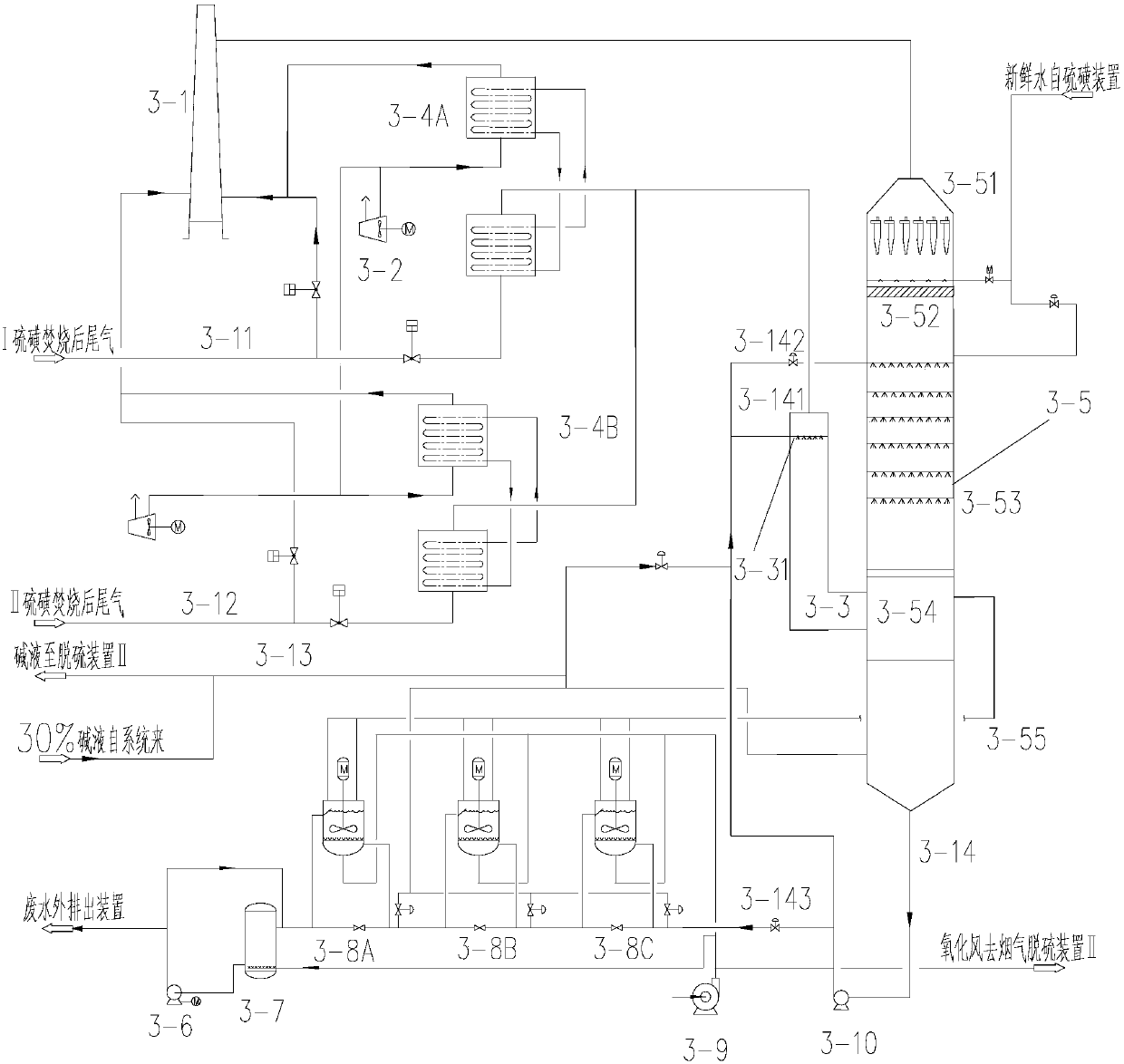
Relating to methods and devices for deep desulfurization and alkali control of sulfur incineration tail gas by sodium process, the invention provides a method for deep desulfurization and alkali control of sulfur incineration tail gas by sodium process. The method includes the steps of: (A) subjecting the sulfur incineration tail gas to air cooling, then letting the cooled tail gas enter a desulfurization tower quenching section, and then introducing the tail gas into a desulfurization tower body; (B) ) in the desulfurization tower body, enabling the tail gas to enter the spray zone of the desulfurization tower from the lower part, and performing multilayer spraying of a circulating absorbent to ascending gas for reaction to absorb most of the sulfur in the tail gas; (C) letting the tail gas carrying atomized droplets ascend to the swirling flow zone of the desulfurization tower and enter swirling flow tubes for further contact absorption of alkaline droplets and non-fully reacted sulfur dioxide to strengthen the desulfurization effect, and letting the alkaline droplets gather and drip from the lower openings of the swirling flow tubes to flow back into the desulfurization tower body; and (D) mixing the purified gas obtained in step (C) with the heated air in step (A), and then discharging the mixed gas into the atmosphere together. The invention also provides a device for deepdesulfurization and alkali control of sulfur incineration tail gas by sodium process.

Description

technical field [0001] The disclosure belongs to the field of flue gas treatment and environmental protection, especially sulfuric acid-containing gas produced in the oil refining process, and relates to a desulfurization separation device, which provides a method for deep desulfurization and alkali control of tail gas after sulfur incineration, so as to realize deep purification of tail gas And lye consumption control, to achieve a win-win environment and economic benefits. Specifically, the disclosure relates to a method and device for deep desulfurization and alkali control of tail gas after sulfur incineration. Background technique [0002] The role of the sulfur recovery unit is to recover sulfur from the acid gas containing hydrogen sulfide produced in the oil refining process by using appropriate processes to achieve clean production, turn harm into profit, turn waste into wealth, reduce pollution, and protect the environment. At the same time, it meets the requireme...

Claims


Application Information

Patent Timeline
Patent Type & Authority Applications(China)
IPC IPC(8): B01D53/50B01D50/00B01D53/78
CPCB01D53/501B01D2258/0283B01D2251/304B01D2251/604B01D50/40
Inventor 方乙琳汪华林沈其松李剑平吴文锋
Owner ZHENHAI PETROCHEMICAL ENG CO LTD
Learn More