Percutaneous left heart drainage tube

A technology of drainage tube and left ventricle, applied in the direction of catheter, coating, etc., can solve the problems of reducing and increasing cardiac output, thrombocytopenia, etc., and achieve the effect of simplifying the operation process and reducing ventricular load

Pending Publication Date: 2019-07-12
李庆国
View PDF7 Cites 2 Cited by
  • Summary
  • Abstract
  • Description
  • Claims
  • Application Information

AI Technical Summary

Problems solved by technology

Disadvantages: This intubation method causes an increase in left ventricular afterload, resulting in blood stasis in the left ventricle, which may lead to an increase in left ventricular end-diastolic pressure (LVEDP), pulmonary capillary wedge pressure (PCWP) and The reduction in stroke volume further exacerbates left ventricular hyperemia, and there is a risk of hemorrhage at the puncture cannula site and risk of distal limb ischemia
[0006] Intra-aortic balloon pump (IABP) consists of a 7.0-8.0Fr double-lumen catheter and a cylindrical polyethylene balloon. The balloon passes through the femoral or axillary artery through the delivery sheath. Placed in the aorta, disadvantages: cannot significantly increase cardiac output, has potential risks such as limb ischemia, vascular trauma, thrombosis, hemolysis, and thrombocytopenia
Disadvantages: Small axial flow pump...

Method used


Image

  • Percutaneous left heart drainage tube
  • Percutaneous left heart drainage tube
  • Percutaneous left heart drainage tube

Examples


Embodiment Construction

[0030] The present invention will be further described in detail below in conjunction with the accompanying drawings and specific embodiments.

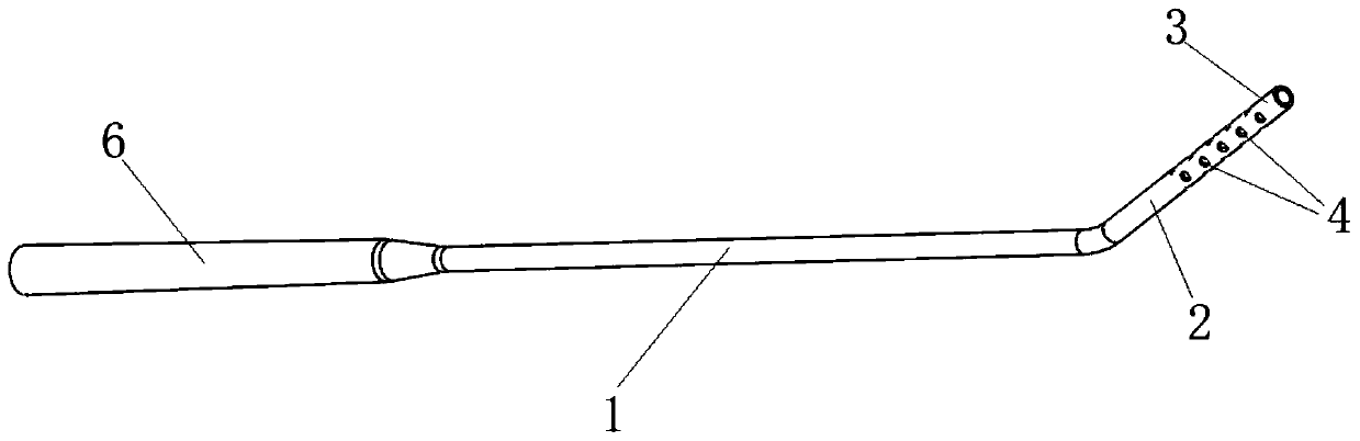
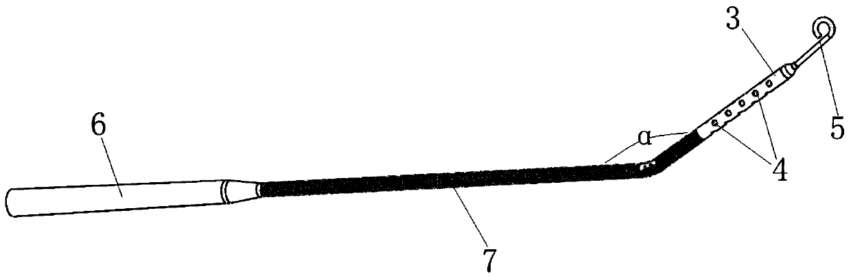
[0031] like figure 2 , 3 As shown, the percutaneous left heart drainage tube is made of medical PVC or new polyurethane tube, and the surface is covered with polyvinylpyrrolidone (PVP) highly hydrophilic polymer coating, which significantly reduces the friction coefficient and facilitates tube placement. The ventricular segment and the arterial segment 1 located in the left ventricular external artery, the gauge of the ventricular segment and the arterial segment 1 is 21Fr. The angle α between the ventricular segment and the arterial segment 1 is 165° (160° to 175° is acceptable). In order to fix the angle between the ventricular segment and the arterial segment 1, the ventricular segment and the arterial segment 1 are connected There is a metal positioning ring, which is not marked in the figure. The setting of the metal locating...


PUM

PropertyMeasurementUnit
Angleaaaaaaaaaa

Abstract

The invention discloses a percutaneous left heart drainage tube, which comprises a ventricular segment positioned in a left ventricle and an artery segment (1) positioned in an external artery of theleft ventricle, wherein the included angle between the ventricular segment and the artery segment (1) is 160-175 degrees; the ventricular segment consists of an inhalation segment (3) and a non-inhalation segment (2); the inhalation segment (3) is positioned at the tail end; a plurality of inhalation side holes (4) are formed in the wall of the inhalation segment (3); a plastic spring ring (7) sleeves outside the non-inhalation segment (2) and the artery segment (1); the percutaneous left heart drainage tube can be inserted through the axillary artery or the carotid artery, the operation flowis simplified, and the ventricular assist device can be coordinated to achieve left heart drainage. The drainage catheter is directly arranged in the left ventricle under the guidance of cardiac ultrasound or DSA through the peripheral vessel, and high-risk invasive operations such as atrial septum puncture or ventricular opening and the like are not needed; in addition, the percutaneous left heart drainage tube can effectively drain left ventricle blood, and the ventricular load is reduced through the catheter in ventricular assistance.

Description

technical field [0001] The invention relates to a left heart drainage tube, in particular to a percutaneous left heart drainage tube, which belongs to the technical field of medical devices. Background technique [0002] Heart failure is a worldwide public health problem with high morbidity, poor prognosis and heavy economic burden. The incidence rate of people aged 30-65 years is 1.5-2% worldwide, and the incidence rate of people over 65 years old is 6-10%, and the incidence rate continues to rise. Treatment of heart failure includes drug therapy, cardiac resynchronization therapy, heart transplantation, and mechanically assisted circulation. Although the drug treatment of heart failure has been continuously optimized, studies have shown that the overall 5-year survival rate does not exceed 50%, and the survival rate of end-stage heart failure is even lower. [0003] Ventricular assist device can reduce the work of the heart and provide circulatory support. Since it was u...

Claims


Application Information

Patent Timeline
IPC IPC(8): A61M25/00A61M25/098
CPCA61M25/0045A61M25/007A61M25/0021A61M2025/0046A61M2025/0008
Inventor 李庆国管翔
Owner 李庆国
Why Eureka
Try Eureka