Method for boiler flue gas multi-stage heat exchange white smoke removal

A technology for boiler flue gas and flue gas, applied in separation methods, chemical instruments and methods, gas treatment, etc., can solve problems such as flue gas tailing, achieve the effect of eliminating flue gas tailing and improving efficiency

Active Publication Date: 2019-08-09
河南迪诺环保科技股份有限公司
View PDF3 Cites 4 Cited by
  • Summary
  • Abstract
  • Description
  • Claims
  • Application Information

AI Technical Summary

Problems solved by technology

These fine dusts are difficult to capture and remove, making it difficult for saturated flue gas to diffuse and form tailings. During the denitrification process, ammonia escapes to generate ammonium sulfate to form aerosols, resulting in flue gas tailings. A large number of smoke plumes float in the air, forming fog. One of the causes of haze

Method used


Image

  • Method for boiler flue gas multi-stage heat exchange white smoke removal
  • Method for boiler flue gas multi-stage heat exchange white smoke removal
  • Method for boiler flue gas multi-stage heat exchange white smoke removal

Examples


Embodiment 1

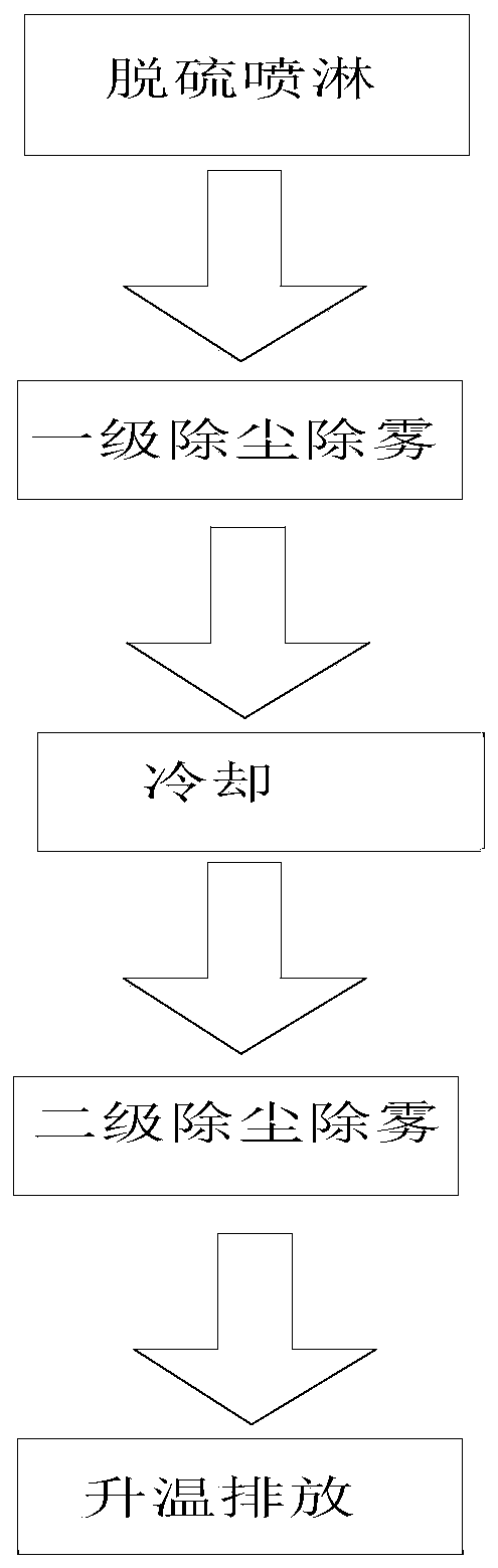
[0053] Such as figure 1 As shown, a method for multi-stage heat exchange dewhitening of boiler flue gas comprises the following steps:

[0054] S1: Desulfurization spraying, the boiler flue gas enters the desulfurization tower for desulfurization by spraying, the flue gas enters from the lower part of the desulfurization spraying area and contacts the desulfurization spraying liquid countercurrently, after passing through the desulfurization spraying area, it is saturated or nearly saturated by water vapor, and the flue gas After desulfurization and spraying, the temperature drops to 55-70°C; S2: first-stage dust and fog removal, the flue gas after S1 desulfurization continues to flow to the upper part of the desulfurization tower at a flow rate of 5m / s-10m / s, and enters the first-stage swirl plate Dust and mist eliminator, under the guidance of the swirl plate, the flue gas rotates at a high speed in the swirl plate dust and mist eliminator to remove water mist and fine dust ...

Embodiment 2

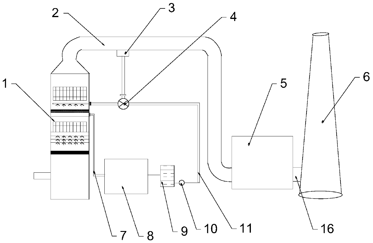
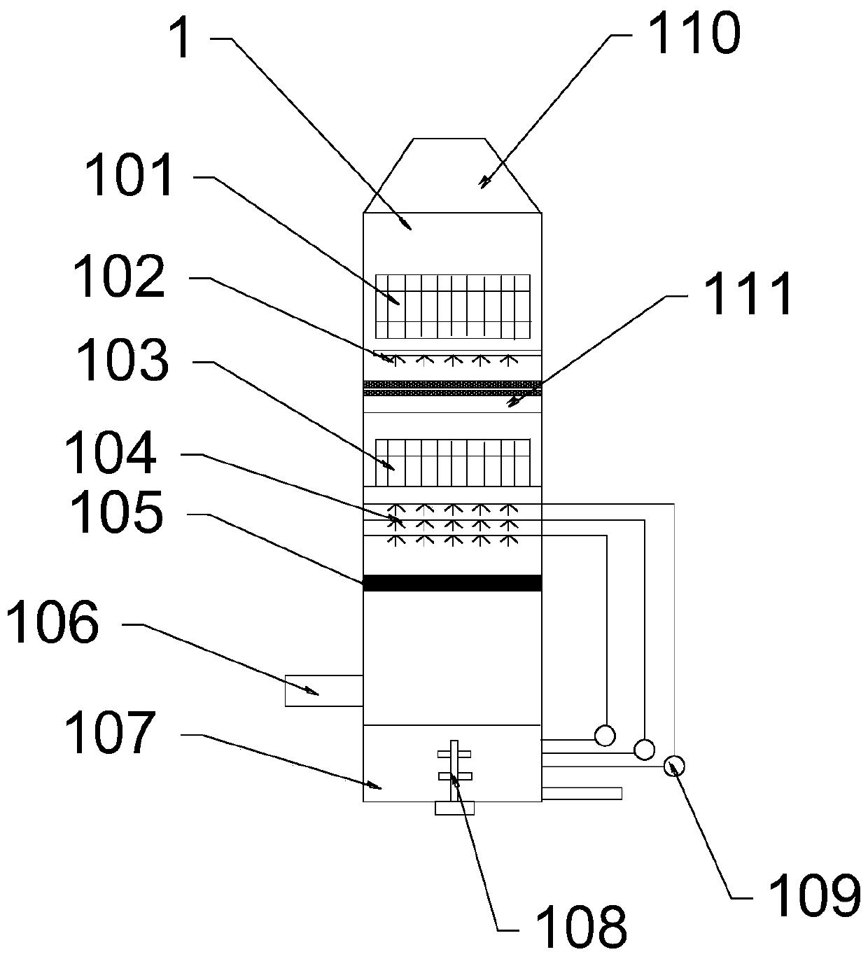
[0059] Such as figure 2 As shown, the first spray pipe 104 is connected to the slurry tank 107 through a circulation pump 109, the slurry tank 107 is provided with an agitator 108, and the first spray pipe 104 is provided with at least two layers. Further, the The flue gas inlet of the desulfurization tower is connected to the boiler through a dust collector and an induced draft fan in sequence, and the end of the slurry tank far away from the air inlet is provided with a liquid discharge port, and the liquid discharge port is connected to a cyclone, and the liquid collection tank is drained by a circulating pump 109. The desulfurization liquid in 107 is sprayed into the desulfurization tower 1 through the first spray pipe 104, sprayed to the reaction area after being atomized by the nozzle, and the contact area between the slurry and the flue gas is increased to realize the desulfurization of the flue gas. There are conventional agitators with technology, the agitator 108 st...

Embodiment 3

[0061] Described heat exchanger 105 adopts any one of glass plate, silicon carbide ceramic tube, fluoroplastic heat exchanger, preferred heat exchanger 105 adopts fluoroplastic heat exchanger, and the pipe diameter of described fluoroplastic heat exchanger is 10 ~50mm, wall thickness 1~1.5mm, the fluoroplastic heat exchanger adopts modular design, the tube bundle includes 600~5000 tubes, the tubes are separated and fixed by fluoroplastic coils, fluoroplastic Strong corrosion resistance, stable chemical properties, can be used normally in the range of -190 ° C ~ 220 ° C, smooth surface and moderate flexibility, not easy to scale, low smoke resistance, aging resistance, long service life and self-cleaning Function.


PUM

PropertyMeasurementUnit
Diameteraaaaaaaaaa

Abstract

The invention relates to a method for boiler flue gas multi-stage heat exchange white smoke removal. The method comprises the following steps of S1, desulfurization spraying, wherein boiler flue gas enters a desulfurization tower for spraying desulfurization, and is saturated by water vapor or approaches to be saturated after passing through a desulfurization spraying region; S2, primary dust removal and mist removal, wherein the flue gas obtained after desulfurization in S1 enters a first stage rotational flow plate dust removal mist eliminator, and mist and fine dust particles in flue gas are removed; S3, cooling, wherein the flue gas obtained after dust removal mist eliminator in S2 flows to a cooling spraying liquid collecting region, and water vapor in the flue gas is separated out; S4, secondary dust removal and mist removal, wherein the flue gas obtained after cooling in S3 enters a secondary rotational flow plate dust removal mist eliminator, mist and fine dust particles in theflue gas are removed for the second time, the flue gas reaches the degree of saturation, and the flue gas is exhausted from a desulfurization tower; S5, heating and discharging, wherein flue gas exhausted in S4 enters a heat exchanger, after heating is performed through the heat exchanger, the degree of saturation of the flue gas is lowered, and the flue gas is exhausted to the atmosphere througha chimney.

Description

technical field [0001] The invention belongs to the technical field of boiler flue gas treatment technology, and in particular relates to a method for multistage heat exchange dewhitening of flue gas. Background technique [0002] The "white smoke" phenomenon occurs when industrial heating furnaces and power plant boilers discharge flue gas into the atmosphere, mainly because the hot flue gas meets the air, the temperature of the flue gas decreases, the moisture contained in it reaches supersaturation, and the water vapor condenses to form white mist . [0003] The reduction of "white smoke" has a positive effect on improving the appearance of flue gas emissions and increasing public environmental acceptance. With the improvement of air pollutant emission standards, a large number of flue gases from industrial furnaces and power plant boilers are discharged after desulfurization and denitrification, and wet desulfurization is adopted The flue gas carries saturated water vap...

Claims


Application Information

Patent Timeline
IPC IPC(8): B01D50/00B01D53/18
CPCB01D53/18B01D53/1481B01D2258/0283B01D50/40
Inventor 李愉张志勇王莉李硕
Owner 河南迪诺环保科技股份有限公司
Why Eureka
Try Eureka