Oil sludge drying system and method for drying oil sludge through system in cooperation with chemical agent

A chemical agent, drying technology, applied in chemical instruments and methods, sludge treatment, water/sludge/sewage treatment, etc. Accelerate the natural evaporation of water, good economic feasibility, and the effect of industrialization.

Active Publication Date: 2019-08-09
广安铭鸿环保科技有限责任公司
View PDF13 Cites 4 Cited by
  • Summary
  • Abstract
  • Description
  • Claims
  • Application Information

AI Technical Summary

Problems solved by technology

Among them, the method invented in the document CN 109231749 A requires low-temperature drying at 120-150°C, which not only consumes high energy, but also the light hydrocarbons in the oil sludge volatilize during the drying process, and there is a risk of explosion. If safety facilities are added, the cost will be further increased; The device invented by CN 202529971 U is an economical natural drying method. However, when it is used for oil sludge, it also has the safety problem of light hydrocarbon volatilization, the oil sludge often smells due to sulfur, etc., and the machine cannot work on the drying bed. The key point is that the device only relies on sunlight for natural drying, which is not only limited by sunlight, but also after a large amount of water in the sludge evaporates naturally, the air humidity in the confined space increases, the saturated vapor pressure increases, and when the evaporation in the sludge is reached After the pressure is balanced, the evaporation rate will be significantly reduced, which is not conducive to sludge drying, and the dehydration efficiency of the technical scheme of the invention is low; although the dehydration process invented by the document CN109574457 A uses 30°C to 40°C low-temperature hot air drying, the entire reaction process The time is long, and a large amount of inorganic strong acid is used in the reaction process, and there is a very large safety hazard in the strong oxidation reaction process. Such a large amount of inorganic strong acid poses a huge threat to the operator during transportation, loading and unloading, storage, and use. threats of personal injury
[0013] There are also some drying devices dedicated to oil sludge. The patent with the publication number of CN107695090A forms low-temperature and high-temperature regions through the inner cylinder and the outer cylinder to dry the sludge. However, for viscous sludge, the rotation of the inner cylinder is easy to accumulate materials. All abilities are limited
This type of drying device is a traditional drying method, and the main heat transfer method is heat transfer. However, due to the high water content in high-moisture sludge, this heat transfer method is relatively slow, which affects the processing capacity, prolongs the processing process, and increases the heat. loss
[0014] From the above analysis, it can be seen that natural drying, chemical agent drying, drying equipment drying and other methods for oil sludge with a moisture content of 60% to 90% cannot meet the requirements in terms of treatment time, treatment efficiency, economy and safety. achieve reduction

Method used


Image

  • Oil sludge drying system and method for drying oil sludge through system in cooperation with chemical agent
  • Oil sludge drying system and method for drying oil sludge through system in cooperation with chemical agent
  • Oil sludge drying system and method for drying oil sludge through system in cooperation with chemical agent

Examples


Embodiment 1

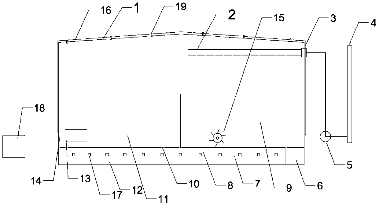
[0058] A sludge drying system, mainly composed of a drying chamber, a drying bed 10, a ventilation system, an auxiliary heating system, and a liquid accumulation system. The length, width, and height of the drying chamber = 40.0m×15.0m×4.0m, and a herringbone ceiling 1 , the distance between the herringbone ceiling 1 and the heavy-duty floor 8 of the drying chamber is 9.5m, and the drying bed 10 consists of a 0.2m heavy-duty floor 8, a 0.02m floor heating radiator 17, a heat insulation layer 7, and a 1.0m anti-corrosion chamber from top to bottom. Infiltration layer 12, the ventilation system is composed of an air inlet pipe 14 with a diameter of 1.0m, a drying tank 13, an air outlet pipe 2 with a diameter of 0.5m, an induced draft fan 3, a burner 5, and a chimney 4; the air outlet pipe 2 and the induced draft fan 3, The burner 5 and the chimney 4 are connected, and the air inlet pipe 14 and the air outlet pipe 2 are respectively arranged on the two left and right walls of the ...


PUM


Abstract

The invention discloses an oil sludge drying system and a method for drying oil sludge through the system in cooperation with a chemical agent. The system is composed of a drying chamber, a drying bed, a ventilation system, an auxiliary heat system, a liquid accumulation system and a turner, the drying chamber is composed of a ceiling and surrounding walls, and the drying chamber and the drying bed form a closed space; the drying bed is composed of heavy load ground, a heat insulation layer and an impermeable layer, the ventilation system is composed of an air inlet pipe, a drying tank, an airoutlet pipe, an induced draft fan, a burner and a chimney, and the auxiliary heat system is composed of a heat source and a radiator; the liquid accumulation system is composed of a liquid accumulation ditch and a liquid accumulation tank. A solid surfactant, a coagulant, CaO and cement are added to the oil sludge according to a certain proportion for even mixing, the mixture is flat laid and stacked in the drying chamber, and under the condition of forced ventilation, the water content is lowered by 30% or above within 5 days. According to the system and the method, the methods such as low-temperature auxiliary heat, forced ventilation, natural drying and the chemical agent are integrated, and the system has the advantages of being simple in structure, convenient to operate and low in cost and has good application prospects.

Description

technical field [0001] The invention relates to the technical field of environmental protection, in particular to an oil sludge drying technology for industrialization, in particular to an oil sludge drying system and a method for synergistically drying oil sludge with chemical agents. Background technique [0002] Oil and natural gas are important energy sources and an important pillar of the national economy. Oil sludge is an associated waste in the process of oil and natural gas extraction. Most of the oil sludge has a high moisture content: [0003] (1) After the oily sewage is broken, flocculated and solid-liquid separated, the moisture content of the sludge is 60% to 90%; [0004] (2) The moisture content of oil sludge in the joint station is 50% to 80%; [0005] (3) Oil sludge after thermal cleaning, extraction, etc., with a water content of 60% to 80%; [0006] (4) The water content of oil sludge after sewage treatment in refinery plants is 70% to 90%. [0007] Th...

Claims


Application Information

Patent Timeline
Patent Type & Authority Applications(China)
IPC IPC(8): C02F11/13C02F11/143C02F11/145C02F11/147
CPCC02F11/13C02F11/143C02F11/145C02F11/147
Inventor 刘宇程王茂仁陈明燕廖茂芪祝梦甘冬
Owner 广安铭鸿环保科技有限责任公司
Why Eureka
Try Eureka