
Landfill leachate treatment method for garbage transfer station

A technology of landfill leachate and waste transfer station, which is applied in the field of landfill leachate treatment in waste transfer stations, which can solve problems such as potential safety hazards, large amount of concentrated water, secondary pollution of waste gas, etc., and achieve the effect of avoiding cost waste and strong practicability

Inactive Publication Date: 2019-08-30
JIANGSU YUMING GRP
View PDF5 Cites 13 Cited by
  • Summary
  • Abstract
  • Description
  • Claims
  • Application Information

AI Technical Summary

Problems solved by technology

[0004] 1. Pre-anaerobic treatment of wastewater can save energy to a certain extent and can comprehensively recover biogas energy. However, the biogas generated after anaerobic treatment is flammable and explosive, and the location of the garbage transfer station is usually close to residents. Districts and downtown areas, and there are a large number of sanitation transport vehicles entering and leaving, the direct combustion of biogas or the reuse of biogas collection, there are certain safety hazards and secondary pollution of exhaust gas (hydrogen sulfide, sulfur dioxide, etc.), so the anaerobic treatment process Restricted at waste transfer stations;
[0005] 2. In the conventional landfill leachate treatment process, the double-membrane treatment process of ultrafiltration and reverse osmosis is mostly used, which can stabilize the water quality; but the investment in membrane treatment and the cost of replacing the membrane are high, and the amount of concentrated water produced by reverse osmosis Larger, concentrated water evaporation and crystallization equipment and operating costs are higher; therefore, there is an urgent need for a non-film advanced treatment technology to replace the mainstream double-film treatment process

Method used


Image

  • Landfill leachate treatment method for garbage transfer station

Examples


Embodiment 1

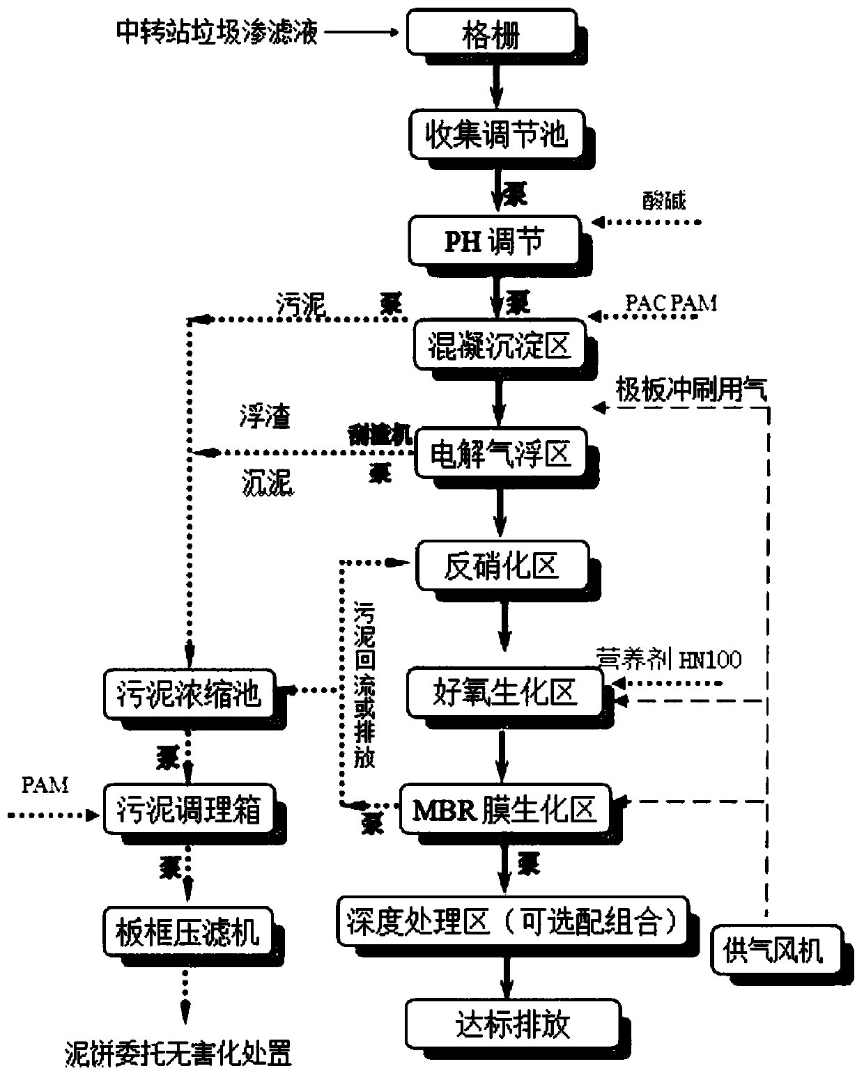
[0065] Step 1: First filter the landfill leachate through the grid, and then pass it into the collection and adjustment tank, control the hydraulic retention time of the material to 6h, adjust the water quality, and obtain the primary mixed solution; then adjust the PH, and lift the primary mixed solution through the pump Enter the pH adjustment tank, under the automatic control of the pH online controller, add alkaline chemicals to adjust the pH value, adjust the pH of the primary mixed solution to 8; after pH adjustment, pass the primary mixed solution into the coagulation tank, and add PAC , PAM coagulant agent, after coagulation for 10 minutes, easy-to-precipitate flocs are formed to obtain a mud-water mixture; the mud-water mixture enters the sedimentation tank for mud-water separation to remove precipitated particles, impurities and heavy metal pollutants. After separation, a supernatant is obtained, and the separation produces The sludge and scum are discharged into the ...

Embodiment 2

[0075] Step 1: First filter the landfill leachate through the grid, and then pass it into the collection and adjustment tank, control the hydraulic retention time of the material to 8h, adjust the water quality, and obtain the primary mixed solution; then adjust the PH, and lift the primary mixed solution through the pump Enter the pH adjustment tank, under the automatic control of the pH online controller, add alkaline chemicals to adjust the pH value, adjust the pH of the primary mixed solution to 8.5; after pH adjustment, pass the primary mixed solution into the coagulation tank, and add PAC , PAM coagulant agent, after coagulation for 13 minutes, easy-to-precipitate flocs are formed to obtain a mud-water mixture; the mud-water mixture enters the sedimentation tank for mud-water separation to remove precipitated particles, impurities and heavy metal pollutants. After separation, a supernatant is obtained, and the separation produces The sludge and scum are discharged into th...

Embodiment 3

[0084] Step 1: First filter the landfill leachate through the grid, and then pass it into the collection and adjustment tank, control the hydraulic retention time of the material to 10h, adjust the water quality, and obtain the primary mixed solution; then adjust the PH, and lift the primary mixed solution through the pump Enter the pH adjustment tank, under the automatic control of the pH online controller, add alkaline chemicals to adjust the pH value, adjust the pH of the primary mixed solution to 9; after pH adjustment, pass the primary mixed solution into the coagulation tank, and add PAC , PAM coagulant agent, after coagulation for 15 minutes, easy-to-precipitate flocs are formed to obtain a mud-water mixture; the mud-water mixture enters the sedimentation tank for mud-water separation to remove precipitated particles, impurities and heavy metal pollutants. After separation, a supernatant is obtained, and the separation produces The sludge and scum are discharged into the...


PUM

PropertyMeasurementUnit
decomposition efficiencyaaaaaaaaaa

Abstract

The invention discloses a landfill leachate treatment method for a garbage transfer station. Firstly a flocculation method is used to remove particulate matters and part of heavy metal ions in a leachate to reduce the subsequent treatment pressure and reduce the treatment cost, the leachate is further treated by an electrolysis air flotation manner to remove fine particles and impurities in the leachate, the high concentration ammonia nitrogen in the leachate is removed by a stripping process, microorganisms are used to remove the organic matter pollution in the leachate, finally the leachateis subjected to deep treatment, and the selection matching is carried out according to requirements of outlet water to ensure that the discharge of wastewater is up to standards. The method does not use an anaerobic treatment process, reduces the generation amount of odor gases, is beneficial to the environment of a treatment zone, avoids the occurrence of biogas combustion, improves the safety ofthe entire apparatus, and is more practical. The method can make discharge indexes of the wastewater obtained after the landfill leachate treatment meet requirements, and thus the method is environment-friendly and practical.

Description

technical field [0001] The invention relates to the technical field of garbage leachate treatment, in particular to a garbage transfer station garbage leachate treatment method. Background technique [0002] Before the garbage is collected, packaged and transferred in the garbage transfer station, a certain amount of landfill leachate will be produced in the transfer station, generally about 10% of the total amount of garbage. The treatment plant conducts treatment, but the transportation cost of the waste water transfer process is high, and it is easy to cause secondary pollution. Therefore, the landfill leachate should be treated in the waste transfer as much as possible to reduce pollution and protect the environment. [0003] From the point of view of the current landfill leachate treatment process, the combination of pretreatment, biological treatment (anaerobic, aerobic) and advanced treatment (membrane method, evaporation crystallization) is more common, which can eff...

Claims


Application Information

Patent Timeline
Patent Type & Authority Applications(China)
IPC IPC(8): C02F9/14C02F11/12C02F11/147C02F11/122C02F103/06
CPCC02F1/32C02F1/465C02F1/5245C02F1/56C02F1/66C02F3/12C02F3/1268C02F9/00C02F11/12C02F11/122C02F11/14C02F2103/06
Inventor 王明吉中波罗茂林曹松张兵
Owner JIANGSU YUMING GRP
Learn More