

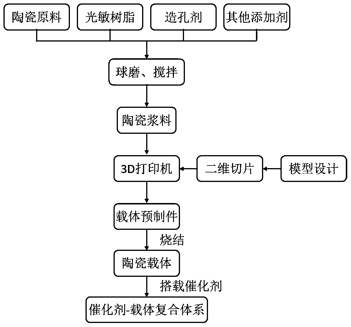
Method for 3D printing of catalyst-carrier system with high specific surface area and high efficiency
A high specific surface area, 3D printing technology, applied in the field of additive manufacturing, can solve the problems such as the inability to control the microscopic morphology and pore structure of the carrier material, the lightweight, controllable structure and high specific surface area of the carrier material, etc. The morphology and pore structure are simple and controllable, avoiding structural deformation, and the effect of high specific surface area
- Summary
- Abstract
- Description
- Claims
- Application Information
AI Technical Summary
Problems solved by technology
Method used
Image

Examples
Embodiment 1
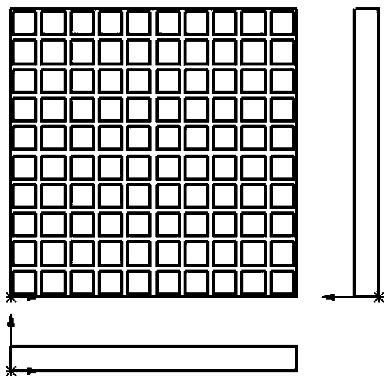
[0036] Design the carrier structure through SolidWorks software, the bottom plate is 10*10*0.8mm 3 For a square sheet, the designed geometric array unit has a square hole with a side length of 0.8mm and a depth of 0.8mm, and the wall thickness between adjacent holes is 0.2mm, such as figure 2 shown. Slice through the software bound by the 3D printer manufacturer, the thickness of the slice is 50 μm, add 3 layers of bottom plate, and import it into the 3D printer. Weigh 50wt.% of alumina powder, 1wt.% of trimethylbenzoyl-diphenylphosphine oxide, 1wt.% of Triton X-100, 2wt.% of magnesium oxide, 2wt.% of silicon oxide and 16wt.% of sodium chloride. %, mixed by ball mill for 48h. The obtained powder was added into 30 wt.% photocurable resin stirred at 120 r / min at a rate of 5 g / min, and the stirring was continued for 8 hours to obtain a ceramic slurry. The parameters of the 3D printer were set to 6000ms for the exposure time of the upper layer, 3000ms for the resting time for ...
Embodiment 2
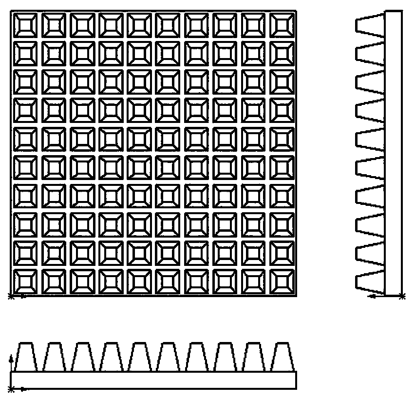
[0038] Design the carrier structure through SolidWorks software, the bottom plate is 10*10*0.6mm 3 For a square sheet, the geometric array unit designed is a regular quadrangular prism with a side length of 0.8mm on the bottom surface, a side length of 0.4mm on the top surface, and a height of 1mm. The distance between the squares on the bottom of adjacent prisms is 0.2mm, such as image 3 shown. Slice through the software bound by the 3D printer manufacturer, the thickness of the slice is 50 μm, add 3 layers of bottom plate, and import it into the 3D printer. Weigh zirconia powder 40wt.%, trimethylbenzoyl-diphenylphosphine oxide 2wt.%, Triton X-100 2wt.%, magnesium oxide 2wt.%, silicon oxide 2wt.% and polyvinyl alcohol 12wt. %, mixed by ball mill for 72h. The obtained powder was added into 40 wt.% photocurable resin stirred at 180 r / min at a rate of 5 g / min, and the stirring was continued for 10 h to obtain a ceramic slurry. Set the 3D printer parameters as high layer expo...
Embodiment 3
[0040] Design the carrier structure through SolidWorks software, the bottom plate is 10*10*0.8mm 3 For a square sheet, the designed geometric array unit is a frustum-shaped through-hole with a diameter of 0.8 mm on the bottom surface, a diameter of 0.4 mm on the top surface, and a height of 0.8 mm. The distance between the centers of the bottom surfaces of adjacent through-holes is 1 mm, such as Figure 4 shown. Slice through the software bound by the 3D printer manufacturer, the thickness of the slice is 50 μm, add 3 layers of bottom plate, and import it into the 3D printer. Weigh trimethylbenzoyl-diphenylphosphine oxide 2wt.%, Triton X-100 1wt.%, magnesium oxide 2wt.%, silicon oxide 2wt.% and sodium bicarbonate 8wt.%, mix by ball mill for 48h . The obtained powder was added into 55wt.% liquid polycarbosilane and 30wt.% photocurable resin stirred at 120r / min at a rate of 5g / min, and the stirring was continued for 8h to obtain a ceramic slurry. The parameters of the 3D prin...
PUM
 Abstract
Description
Claims
Application Information