Efficient industrial tail-gas waste heat recovery device

A waste heat recovery device and industrial tail gas technology, which is applied in the direction of heat exchanger shell, heat exchange equipment, heat exchanger type, etc., can solve the problems of industrial tail gas waste heat recovery efficiency to be improved, tail gas backflow, etc., to achieve simple structure and avoid backflow , low-cost effect

Pending Publication Date: 2019-09-24
GUANGDONG YEA ENERGY SAVING TECH
View PDF0 Cites 1 Cited by
  • Summary
  • Abstract
  • Description
  • Claims
  • Application Information

AI Technical Summary

Problems solved by technology

However, the existing industrial tail gas waste heat recovery devices are prone to tail gas backflow when recovering tail gas waste heat, and the existing industrial tail gas waste heat recovery devices also need to improve the waste heat recovery efficiency of industrial tail gas

Method used


Image

  • Efficient industrial tail-gas waste heat recovery device
  • Efficient industrial tail-gas waste heat recovery device
  • Efficient industrial tail-gas waste heat recovery device

Examples


Embodiment 1

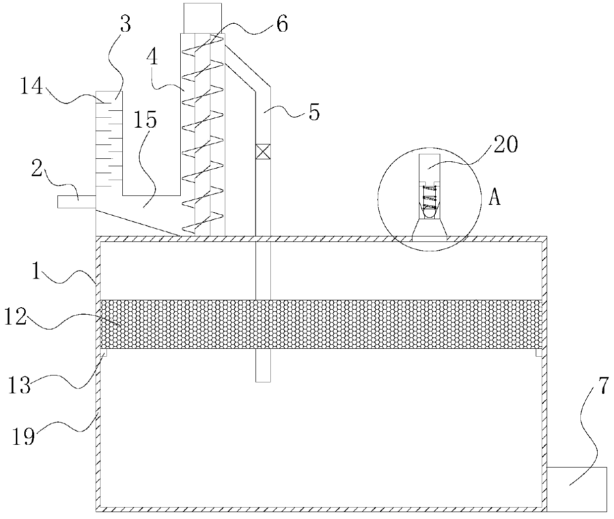
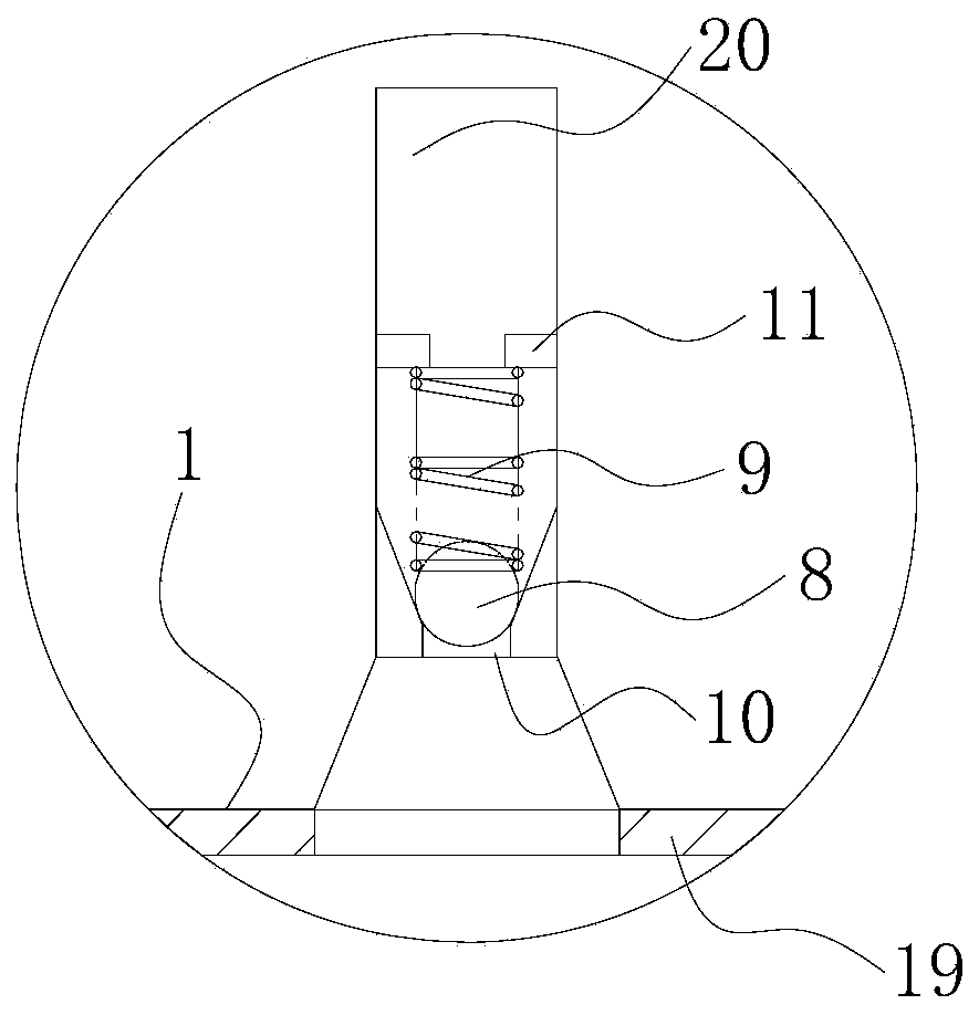
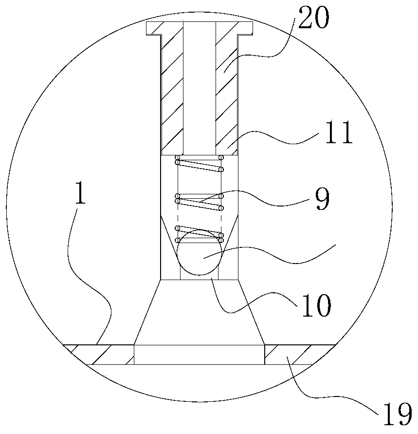
[0028] Such as figure 1 and figure 2 As shown, a high-efficiency industrial tail gas waste heat recovery device in this embodiment includes a liquid storage tank 1, an air inlet pipe 2, a liquid inlet pipe 3 and a water-gas fusion device, and the liquid inlet pipe 3 and the water-gas fusion device are all arranged in the storage tank. The upper end of the liquid tank 1; the water-gas fusion device includes a water-gas fusion channel 4 and a water outlet channel 5, a screw conveyor 6 is arranged on the water-gas fusion channel 4, and one end of the water-gas fusion channel 4 communicates with the upper part of the water-gas fusion channel 4, and the water-gas fusion channel 4 The other end of 5 is set in the liquid storage tank 1; the lower end of the liquid inlet pipe 3 is respectively connected to the lower part of the air intake pipe 2 and the water-air fusion channel 4; the upper end of the liquid storage tank 1 is also provided with an exhaust pipe 20, and the exhaust pip...

Embodiment 2

[0032] This embodiment is a further improvement made on the basis of Embodiment 1. The specific differences between this embodiment and Embodiment 1 are:

[0033] What needs to be further explained in this embodiment is that a filter cotton 12 is provided in the middle of the liquid storage tank 1 , and the other end of the water outlet channel 5 runs through the liquid storage tank 1 below the filter cotton 12 . The filter cotton 12 can prevent the incompletely reacted gas dissolved in the condensed water from being buffered, prolong the reaction time with the condensed water, make the overall reaction time longer, and also make the overall waste heat recovery effect better. At the same time, the sponge can also inhibit the volatilization of heated condensed water and improve the recovery rate of condensed water.

Embodiment 3

[0035] This embodiment is a further improvement made on the basis of Embodiment 2. The specific differences between this embodiment and Embodiment 2 are:

[0036] What needs to be further explained in this embodiment is that a stopper 13 is provided on the inner wall of the liquid storage tank 1 at the lower end of the filter cotton 12 . The stopper 13 can limit the sinking position of the filter cotton 12, preventing the filter cotton 12 from sinking to the bottom of the liquid storage tank 1 when the water level is insufficient at the beginning, so that it is located below the water outlet channel 5 and cannot achieve its own self-protection. effect.


PUM


Abstract

The invention belongs to the technical field of tail-gas treatment, and discloses an efficient industrial tail-gas waste heat recovery device. The efficient industrial tail-gas waste heat recovery device comprises a liquid storage tank, a gas inlet pipe, a liquid inlet pipe and a water-gas fusion device, and the liquid inlet pipe and the water-gas fusion device are both arranged at the upper end of the liquid storage tank; the water-gas fusion device comprises a water-gas fusion channel and a water outlet channel, a spiral conveyer is arranged on the water-gas fusion channel, one end of the water outlet channel communicates with the upper portion of the water-gas fusion channel, and the other end of the water outlet channel is arranged in the liquid storage tank; and the lower end of the liquid inlet pipe communicates with the lower portion of the gas inlet pipe and the lower portion of the water-gas fusion channel respectively, an exhaust pipeline is further arranged at the upper end of the liquid storage tank, and a one-way gas outlet mechanism is arranged in the exhaust pipeline. According to the efficient industrial tail-gas waste heat recovery device, the heat in the tail gas can be fully absorbed by condensate water, so that the effect of efficiently recovering the tail-gas waste heat is achieved. The treatment effect of low-heat-value and low-concentration industrial tail gas can be conveniently improved, and efficient recovery and environment-friendly emission of the waste heat in the industrial tail gas can be realized.

Description

technical field [0001] The invention belongs to the technical field of tail gas treatment, and in particular relates to an efficient industrial tail gas waste heat recovery device. Background technique [0002] Industrial waste gas refers to the general term for all kinds of pollutant gases that are discharged into the air during fuel combustion and production processes in the factory area. These exhaust gases include: carbon dioxide, carbon disulfide, hydrogen sulfide, fluoride, nitrogen oxides, chlorine, hydrogen chloride, carbon monoxide, sulfuric acid (mist) lead mercury, beryllium compounds, smoke and productive dust, which will pollute the air when discharged into the atmosphere. These substances enter the human body through the respiratory tract in different ways, some directly cause harm, and some have a cumulative effect, which will seriously endanger human health. Different substances will have different effects. When the industrial tail gas is discharged, the ta...

Claims


Application Information

Patent Timeline
IPC IPC(8): F28C3/06F28F9/00F28F27/00B01D53/86B01D53/78
CPCF28C3/06F28F9/00F28F27/00B01D53/86B01D53/78
Inventor 谭正莫然陈土贵曲泓俐朱红兵
Owner GUANGDONG YEA ENERGY SAVING TECH
Why Eureka
Try Eureka