Miniaturized foldable nuclear magnetic resonance gyroscope gauge outfit
A nuclear magnetic resonance gyro and magnetic resonance technology, which is applied in the direction of steering induction equipment, etc., can solve the problems of nuclear magnetic resonance gyro head volume, large power consumption, coupling degree, and low integration, so as to facilitate optical installation and improve gyro signal Accuracy, the effect of improving the uniformity of heating temperature
- Summary
- Abstract
- Description
- Claims
- Application Information
AI Technical Summary
Problems solved by technology
Method used
Image
Examples
Embodiment 1
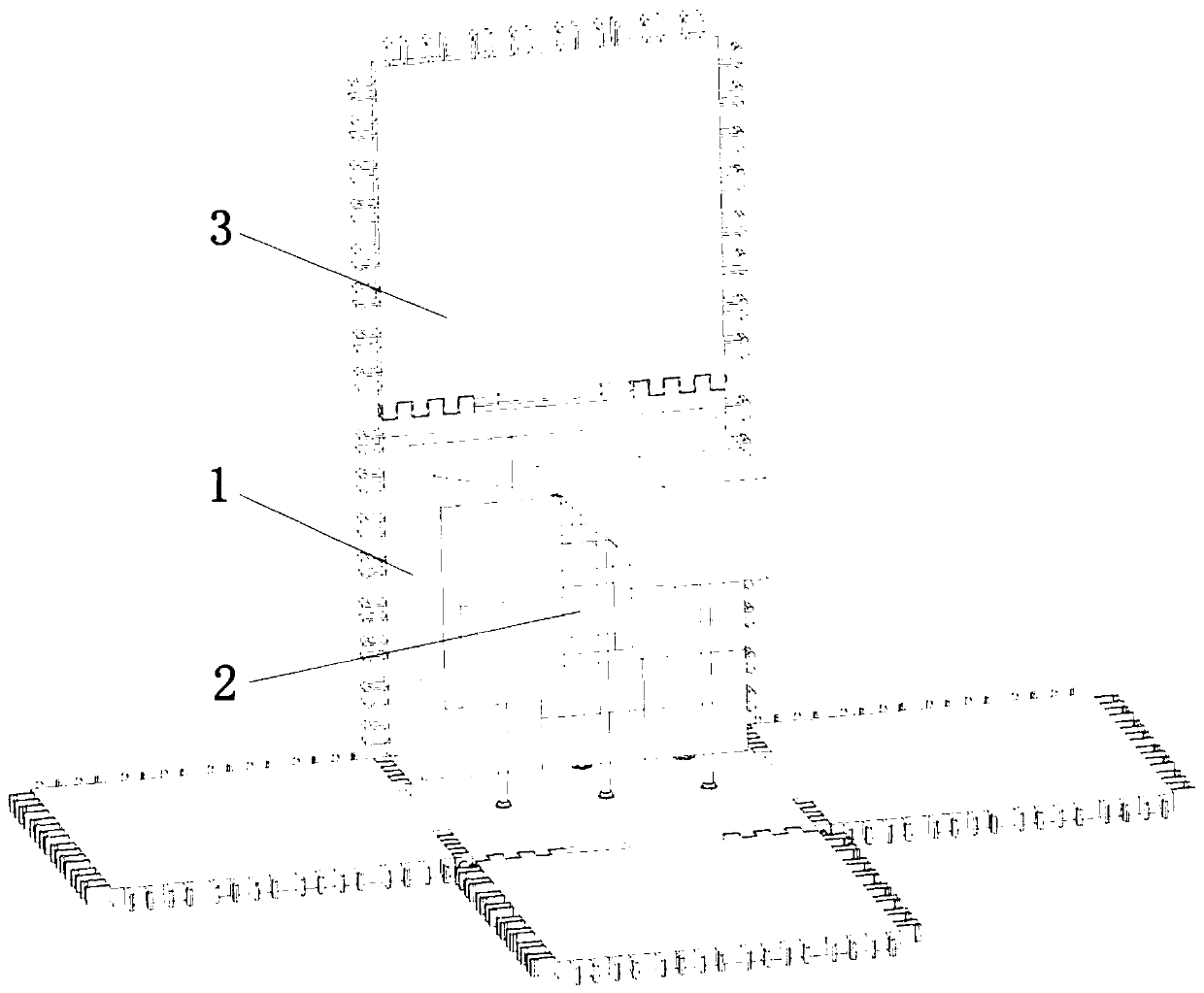
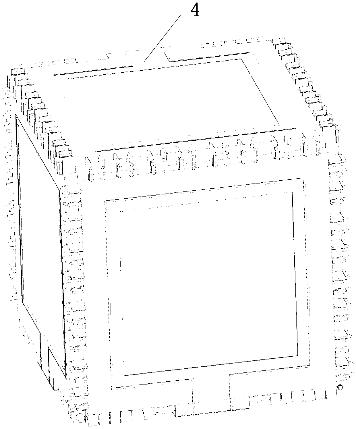
[0041] Example 1, such as figure 1 , 2 shown;
[0042] Miniaturized collapsible MRI gyro instrument head, including:
[0043] A magnetic resonance optical assembly (1); the magnetic resonance optical assembly (1) includes a pumping optical path assembly and a detection optical path assembly;
[0044]An integrated atomic gas chamber (2); the pump light path components work to form pump light, and the detection light path components work to form probe light. Cross-injection; the integrated atomic gas chamber is in the center of the intersection of two beam paths (2);
[0045] Foldable bobbin (3);
[0046] A three-axis coil flexible circuit board (4) for providing a three-axis magnetic field for the gyroscope; the three-axis coil flexible circuit board (4) is installed on the foldable coil skeleton (3).
Embodiment 2
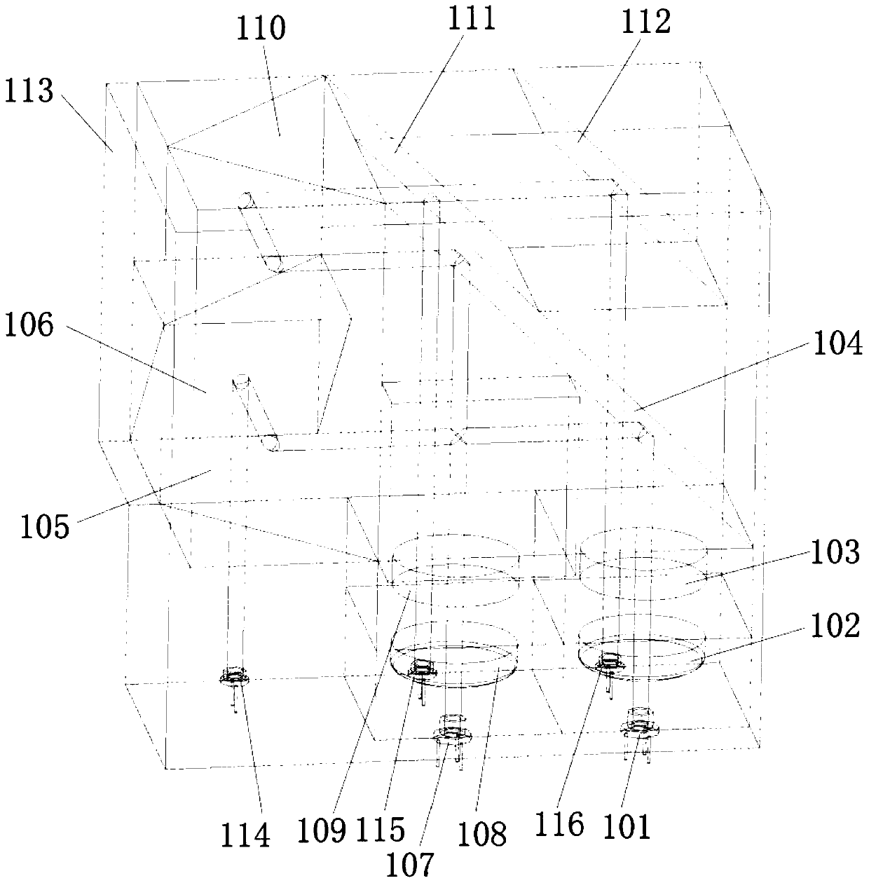
[0047] Example 2, such as image 3 shown;
[0048] The difference between this embodiment and embodiment 1 is:
[0049] The pumping optical path components include micro-laser I (101), aspheric lens I (102), λ / 4 wave plate (103), mirror I (104), mirror II (105), mirror III (106), photodetector I (114),
[0050] Among them, the linearly polarized light generated by the micro-laser I (101) passes through the aspheric lens I (102) and is collimated in parallel. ) as pumping light incident on one side of the integrated atomic gas cell (2) to polarize the alkali metal in it, and the remaining pump light is emitted from the other side of the integrated atomic gas cell (2), and then goes through The reflector II (105) and the reflector III (106) are then injected into the photodetector I (114).
Embodiment 3
[0051] Example 3, such as image 3 shown;
[0052] The difference between this embodiment and embodiment 2 is:
[0053] After the pumping light passes through the mirror I (104), it is perpendicular to the surface of the quartz heating plate I (201) in the integrated atomic gas chamber (2), and after passing through the pumping light of the mirror III (106), it is connected to the micro laser I (101 ) produces linearly polarized light parallel to and vertically incident on the center of the photodetector I (114).
PUM
 Abstract
Description
Claims
Application Information
 - R&D
- Intellectual Property
- Life Sciences
- Materials
- Tech Scout
- Unparalleled Data Quality
- Higher Quality Content
- 60% Fewer Hallucinations
Browse by: Latest US Patents, China's latest patents, Technical Efficacy Thesaurus, Application Domain, Technology Topic, Popular Technical Reports.
© 2025 PatSnap. All rights reserved.Legal|Privacy policy|Modern Slavery Act Transparency Statement|Sitemap|About US| Contact US: help@patsnap.com


