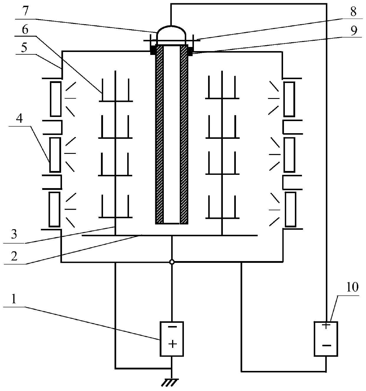
Arc ion plating device with center auxiliary anode
An arc ion plating and auxiliary anode technology, applied in ion implantation plating, sputtering plating, vacuum evaporation plating and other directions, can solve the problem of low coating rate, etc., achieve simple configuration, improve plasma density, plasma density Evenly distributed effect
- Summary
- Abstract
- Description
- Claims
- Application Information
AI Technical Summary
Problems solved by technology
Method used
Image
Examples
Embodiment 1
[0036] In this embodiment, the workpiece 304 stainless steel sheet with a size of 20×20×3 mm was ground, polished, ultrasonically cleaned and dried, and then placed on the workpiece turret of the vertical arc ion plating device. Such as figure 1 As shown, the arc ion plating device mainly includes: vacuum chamber 5, workpiece turret platform 2, workpiece turret 3, workpiece 6, substrate bias power supply 1, arc source target material 4, equipment upper center flange 8, auxiliary anode rod 7 , insulating block 9 and auxiliary anode power supply 10 etc., concrete structure is as follows:
[0037] The workpiece turret 2 is set at the bottom of the vacuum chamber 5, the workpiece turret 3 is set on the workpiece turret 2, the arc source target 4 is set on the side wall of the vacuum chamber 5, and the flange 8 is set at the center of the upper part of the equipment, and the flange 8 One or more auxiliary anode rods 7 are connected to each other. The auxiliary anode rods 7 are mad...
Embodiment 2
[0041] In this embodiment, the workpiece M2 high-speed steel sheet with a size of 20×14×3 mm is ground, polished, ultrasonically cleaned and dried, and placed vertically on the workpiece turret of the arc ion plating device. The difference from Embodiment 1 is that in this embodiment a horizontal arc ion plating equipment is used, the outer diameter of the auxiliary anode rod is 80 mm, and the distance between the auxiliary anode rod and the workpiece turret is 120 mm.
[0042] The arc source target is Ti30Al70at.% alloy target (atomic percentage), and the processed workpiece M2 high-speed steel sample is placed on the workpiece turret. Vacuum until the vacuum degree in the vacuum chamber reaches 8×10 -3 At Pa, argon gas is supplied, the air pressure is controlled at 0.6Pa, the arc-enhanced glow discharge ion etching source is turned on, and the negative bias voltage is applied to the workpiece through the substrate bias power supply in the range of -10V to -250V, and the bias...
Embodiment 3
[0045] In this embodiment, the workpiece M2 high-speed steel sheet with a size of 20×16×3 mm is ground, polished, ultrasonically cleaned and dried, and placed vertically on the workpiece turret of the arc ion plating device. The difference from Embodiment 1 is that in this embodiment a horizontal arc ion plating equipment is used, the outer diameter of the auxiliary anode rod is 100 mm, and the distance between the auxiliary anode rod and the workpiece turret is 90 mm.
[0046] The arc source target is Al67Cr33at.% (atomic percentage) alloy target, and the processed workpiece M2 high-speed steel sample is placed on the workpiece turret. Vacuum until the vacuum degree in the vacuum chamber reaches 7×10 -3 At Pa, argon gas is supplied, and the air pressure is controlled at 0.8Pa. The arc-enhanced glow discharge ion etching source is turned on, and a negative bias voltage is applied to the workpiece through the substrate bias power supply in the range of -10V to -260V, and the bi...
PUM
| Property | Measurement | Unit |
|---|---|---|
| thickness | aaaaa | aaaaa |
| microhardness | aaaaa | aaaaa |
| microhardness | aaaaa | aaaaa |
Abstract
Description
Claims
Application Information
 - R&D
- Intellectual Property
- Life Sciences
- Materials
- Tech Scout
- Unparalleled Data Quality
- Higher Quality Content
- 60% Fewer Hallucinations
Browse by: Latest US Patents, China's latest patents, Technical Efficacy Thesaurus, Application Domain, Technology Topic, Popular Technical Reports.
© 2025 PatSnap. All rights reserved.Legal|Privacy policy|Modern Slavery Act Transparency Statement|Sitemap|About US| Contact US: help@patsnap.com

