Surface-treated copper foil and copper-clad laminate using same

A surface treatment, copper foil technology, applied in the field of copper clad laminates, can solve the problem of multiple pinholes, and achieve the effect of excellent pinhole resistance and high tensile strength

Active Publication Date: 2019-11-19
FURUKAWA ELECTRIC CO LTD
View PDF26 Cites 2 Cited by
  • Summary
  • Abstract
  • Description
  • Claims
  • Application Information

AI Technical Summary

Problems solved by technology

However, the thin copper foil in this copper foil with a carrier is produced using a common copper sulfate bath plating bath, and there is a problem that pinholes frequently occur

Method used


Image

  • Surface-treated copper foil and copper-clad laminate using same
  • Surface-treated copper foil and copper-clad laminate using same
  • Surface-treated copper foil and copper-clad laminate using same

Examples


Embodiment

[0081] Hereinafter, the present invention will be described in detail through examples.

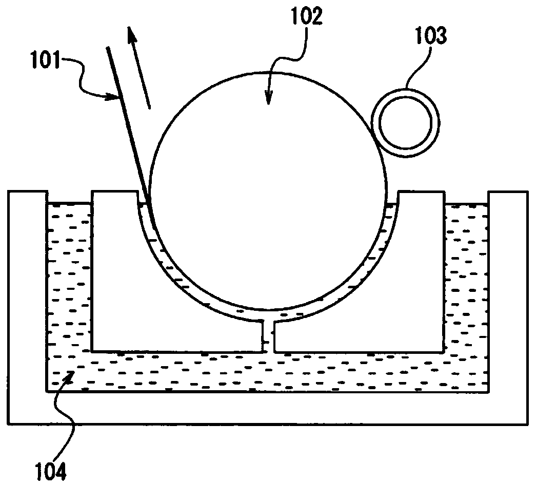
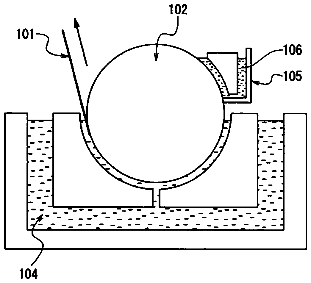
[0082] (1) Manufacture of copper foil and formation of laser absorbing layer

[0083] Electrodeposited copper foils of Examples 1 to 21 and Comparative Examples 1 to 9 were produced through the cathodic reduction step of the electrolytic solution, current density, and bath temperature shown in Table 1, and the electrolytic deposition step based on the electrolysis conditions shown in Table 2. For these electrolytic copper foils, laser absorption was formed by electrolytic plating treatment under the plating bath, treated surface, and electrolytic conditions (pulse voltage pulse width, current density, time, bath temperature) having the composition shown in Table 3, respectively. Floor. In addition, in Example 22, the laser absorption layer was formed by alternating current, and in Example 23, the laser absorption layer was formed by MecEtchBondCZ-8000 treatment. Furthermore, under the e...


PUM

PropertyMeasurementUnit
tensile strengthaaaaaaaaaa

Abstract

Provided is a surface-treated copper foil which has fine line-to-line spaces or line widths, has excellent etching properties, laser processability, and thin foil handling properties, and has less pinholes and a higher tensile strength. The surface-treated copper foil has a tensile strength of 400-700 MPa, a tensile strength of 300 MPa or more after heating at 220 degrees centigrade for 2 hours, afoil thickness of 7 [mu]m or less, a developed area ratio (Sdr) of one side thereof being 25-120%, and the number of pinholes with a diameter of at least 30 [mu]m being 20 / m2 or less.

Description

technical field [0001] The present invention relates to a surface-treated copper foil suitable for a printed wiring board having a high-density wiring circuit (fine pattern) and having excellent laser processability, and a copper-clad laminate using the same. Background technique [0002] A printed wiring board is a copper-clad laminate manufactured by placing a thin copper foil for surface circuit formation on the surface of an electrically insulating substrate made of glass epoxy resin, polyimide resin, etc., and then heating and pressurizing it. Next, through-hole drilling and through-hole plating are sequentially performed on the copper-clad laminate, and then the copper foil of the copper-clad laminate is etched to form a wiring pattern with a required line width and a required line spacing. Finally, solder resist coating, exposure, through-hole plating, or removal of uncured solder resist with caustic soda to expose the plating of the connection portion of the electron...

Claims


Application Information

Patent Timeline
Patent Type & Authority Applications(China)
IPC IPC(8): C25D1/04
CPCC25D1/04H05K1/09H05K3/382
Inventor 佐藤章
Owner FURUKAWA ELECTRIC CO LTD
Why Eureka
Try Eureka