Device and method for follow-up ultrasonic-assisted direct laser deposition of ceramic reinforced metal matrix composite material

A laser deposition, ultrasonic-assisted technology, applied in the field of additive manufacturing, can solve the problems of inconsistent tissue distribution and uneven stress distribution, and achieve the effects of high utilization, uniformity, and consistency.

Active Publication Date: 2019-11-22
DALIAN UNIV OF TECH
13 Cites 16 Cited by

AI-Extracted Technical Summary

Problems solved by technology

[0006] In order to solve the problems of inconsistent tissue distribution and uneven stress distribution in the process of direct laser deposition of ceramic-reinforced metal-matrix composites, the present invention provides a device and method for direct laser-assisted deposition of ceramic-reinforced metal-matrix The clamping device keeps the ultrasonic impact gun and the coaxial powder feeding nozzl...

Abstract

The invention provides a device and a method for follow-up ultrasonic-assisted direct laser deposition of a ceramic reinforced metal matrix composite material, and belongs to the technical field of additive manufacturing. The method comprises the step of adopting a positioning clamping device to keep an ultrasonic impact gun following a coaxial powder feeding nozzle. In the process of direct laserdeposition of the ceramic reinforced metal matrix composite material, ultrasonic cavitation, acoustic streaming, mechanical and thermal effects are utilized to intervene the solidification behavior of a molten pool in real time, and the localized impact strengthening effect of ultrasonic impact is used to control the stress in real time. Compared with the forming method of direct laser deposition, the method can effectively reduce pores inside a sample, and ensure the consistency of the solidified structure and the uniformity of the stress distribution. At the same time, the method has a highutilization rate of ultrasonic energy, and can realize ultrasonic intervention in the forming process of large components.

Application Domain

Technology Topic

Image

  • Device and method for follow-up ultrasonic-assisted direct laser deposition of ceramic reinforced metal matrix composite material

Examples

  • Experimental program(1)

Example Embodiment

[0031] The specific embodiments of the present invention will be further described below in conjunction with the drawings and technical solutions.
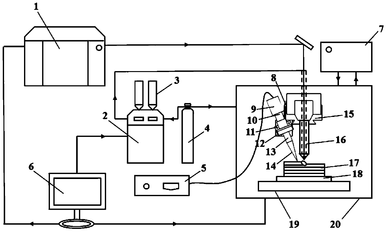
[0032] A follow-up ultrasound assisted direct laser deposition device for ceramic reinforced metal matrix composite materials includes a coaxial powder feeding type laser melting deposition forming system, a positioning clamping device and a follow-up ultrasound system.
[0033] Among them, the coaxial powder feeding laser melting deposition forming system includes a laser 1, a powder feeder 2, a powder feeding cylinder 3, an industrial computer 6, a coaxial powder feeding nozzle 16, a metal substrate 18, a numerical control machine tool 20, a cooling water circulation system 7 and Protective gas system 4. The numerical control machine tool 20 is provided with a dovetail guide rail 15 and a numerical control worktable 19, and a metal substrate 18 is placed on the upper surface of the numerical control worktable 19, and the metal substrate 18 is a TC4 substrate. The coaxial powder feeding nozzle 16 is fixed on the dovetail rail 15. The laser 1 is provided with an optical path system, and the laser emitted by the laser 1 is emitted from the coaxial powder feeding nozzle 16 through the optical path system to form a laser beam on the metal substrate 18; two powder feeding cylinders 3 are connected above the powder feeder 2 for The coaxial powder feeding laser melting deposition forming system provides ceramic powder and metal powder; the powder feeder 2 is connected to the coaxial powder feeding nozzle 16, and the powder sprayed from the coaxial powder feeding nozzle 16 is gathered on the metal substrate 18. Coinciding with the laser beam, a deposition layer 17 is formed. The protective gas system 4 is connected to the powder feeder 2 on one side, and the inert gas is used as the carrier gas to blow the cladding powder from the powder feeder 2 into the molten pool; the other side of the protective gas system 4 is connected to the coaxial powder feeding nozzle 16, As a coaxial protective gas. The cooling water circulation system 7 is connected to the coaxial powder feeding nozzle 16 for cooling the laser head on the coaxial powder feeding nozzle 16. The industrial computer 6 is respectively connected to the laser 1, the powder feeder 2 and the numerical control machine tool 20, and is used to control the laser 1, the powder feeder 2 and the numerical control machine tool 20.
[0034] The positioning and clamping device includes an F-shaped positioning seat 8, a T-shaped manual precision sliding table 12 and an ultrasonic impact gun fixing seat 11. The F-shaped positioning base 8 is fixed on one side of the dovetail guide rail 15, the T-shaped manual precision sliding table 12 is fixed on the F-shaped positioning base 8, and the ultrasonic impact gun fixing base 11 is connected to the T-shaped manual precision sliding table 12 Above, the ultrasonic impact gun fixing seat 11 is used to fix the ultrasonic impact gun.
[0035] The follow-up ultrasonic system includes an ultrasonic generator 5 and an ultrasonic impact gun connected to the ultrasonic generator 5; the ultrasonic impact gun includes a transducer 9, an horn 10, a tool head 13, and an ultrasonic impact needle 14 connected in sequence; The ultrasonic impact gun is fixed on the ultrasonic impact gun fixing seat 11, and the ultrasonic impact gun is positioned directly behind the coaxial powder feeding nozzle 16, so that the ultrasonic impact gun and the coaxial powder feeding nozzle 16 follow.
[0036] Specifically, the protective gas system 4 is high-purity argon.
[0037] The follow-up ultrasonic system, coaxial powder feeding laser melting deposition forming system, and positioning and clamping device that keep the ultrasonic impact gun and the coaxial powder feeding nozzle are used to directly laser deposit TiC and TC4 powder. The specific forming steps are as follows:
[0038] (1) Grind the TC4 substrate with sandpaper, then wipe with acetone, clean with deionized water, and finally blow dry the TC4 substrate. Put the TC4 and TiC powders with a particle size of 25-45μm into an electric blast drying box, and dry them for 4 hours at 150°C. After the TC4 and TiC powders are cooled, put the TC4 and TiC powders into the conveyor. In the two powder feeding cylinders 3 of the powder container 2.
[0039] (2) The F-shaped positioning seat 8 is fixed on the Y-axis dovetail guide rail 15 of the CNC machine tool by the pressing force of the bolt; the F-shaped positioning seat 8 is connected with the T-shaped manual precision sliding table 12 by means of bolt and nut connection. The T-shaped manual precision sliding table 12 is connected with the ultrasonic impact gun fixing seat 11, and the ultrasonic impact gun fixing seat 11 is connected with the ultrasonic impact gun.
[0040] Adjust the angle between the axis of the ultrasonic impact gun and the axis of the coaxial powder feeding nozzle 16 to be 30°. Adjust the ultrasonic impact gun directly behind the coaxial powder feeding nozzle 16, and keep the horizontal distance between the ultrasonic impact needle 14 and the coaxial powder feeding nozzle 16 at 7 mm, so that it is within the maximum plastic deformation zone of the cladding layer. The vertical distance between the coaxial powder feeding nozzle 16 and the TC4 substrate is adjusted to 9 mm, so that the powder converging point of the coaxial powder feeding nozzle 16 is just on the TC4 substrate.
[0041] (3) Turn on the power of the ultrasonic generator 5 to make the ultrasonic impact gun in an ultrasonic vibration state. The ultrasonic power of the ultrasonic generator 5 is set to 800W, and the ultrasonic frequency is 20kHz.
[0042] (4) Turn on the cooling water circulation system 7, the laser 1, the protective gas system 4, and the powder feeder 2 in sequence. The laser power of the laser 1 is set to 400W, and the scanning speed is 300mm/min; each layer is deposited, the CNC machine tool The Z-axis lift is 0.4mm, and the powder feed rate of the powder feeder 2 is 40r/min.
[0043] (5) Turn on the numerical control machine tool 20 and control the movement of the coaxial powder feeding nozzle relative to the TC4 substrate on the numerical control worktable 19 to deposit the first layer of material. At this time, the ultrasonic impact needle 14 acts at 150 μm below the deposition layer 17. This ensures that the ultrasonic impact gun can always act on the deposition layer 17, intervene in the melting process in real time, and implement the control of the stress state. In the Z-axis direction of the lifting amount, the ultrasonic power increases by 140-160W for every 4mm increase in the molding height.
[0044] (6) After forming, turn off the powder feeder 2, the protective gas system 4, the laser 1, the cooling water circulation system 7 and the CNC machine tool 20 in order. The ultrasonic power of the ultrasonic generator 5 is gradually reduced to zero at a speed of 200W/min. Then turn off the ultrasonic generator 5.

PUM

no PUM

Description & Claims & Application Information

We can also present the details of the Description, Claims and Application information to help users get a comprehensive understanding of the technical details of the patent, such as background art, summary of invention, brief description of drawings, description of embodiments, and other original content. On the other hand, users can also determine the specific scope of protection of the technology through the list of claims; as well as understand the changes in the life cycle of the technology with the presentation of the patent timeline. Login to view more.

Similar technology patents

Electric vehicle and power battery active temperature equalization system thereof

InactiveCN107565191AAchieve temperature equalizationEnsure consistencySecondary cellsElectric vehicleEngineering
Owner:NEUSOFT REACH AUTOMOTIVE TECH SHANGHAI CO LTD

Classification and recommendation of technical efficacy words

  • Ensure consistency
  • Guaranteed uniformity

Soybean milk machine with small-space crushing cover

ActiveCN103654475AImproved material crushing effectEnsure consistencyBeverage vesselsEngineeringWater pumping
Owner:JOYOUNG CO LTD

Visual soil freeze-thawing process test apparatus

Owner:NORTHWEST INST OF ECO-ENVIRONMENT & RESOURCES CAS
Why Eureka
Try Eureka