
Low-temperature flash evaporation and light hydrocarbon recovery system and method used for oilfield associated gas

A technology for recovery of associated gas and light hydrocarbons in oilfields, which is applied in the direction of flash evaporation, separation methods, chemical instruments and methods, etc., can solve problems that do not meet national security and environmental protection requirements, affect the economic benefits of enterprises, and are difficult to control associated gas. Reduced emissions, improved efficiency, and reduced adsorption effects

Pending Publication Date: 2019-12-06
HANGZHOU HONGSHENG ZHONGHONG NEW ENERGY CO LTD
View PDF0 Cites 6 Cited by
  • Summary
  • Abstract
  • Description
  • Claims
  • Application Information

AI Technical Summary

Problems solved by technology

[0003] At present, due to the constraints of technical means and the relative difficulty in controlling the associated gas in the oilfield exploitation process, a large part of the associated gas in the oilfield is evacuated or burned, which does not meet the requirements of national security and environmental protection, and also affects the economic benefits of enterprises
The existing associated gas recovery system has the disadvantage of low recovery rate, therefore, it is necessary to improve and optimize the existing associated gas recovery system

Method used


Image

  • Low-temperature flash evaporation and light hydrocarbon recovery system and method used for oilfield associated gas

Examples


Embodiment Construction

[0041] The present invention will be further described in detail below in conjunction with the accompanying drawings and examples. The following examples are explanations of the present invention and the present invention is not limited to the following examples.

[0042] Example.

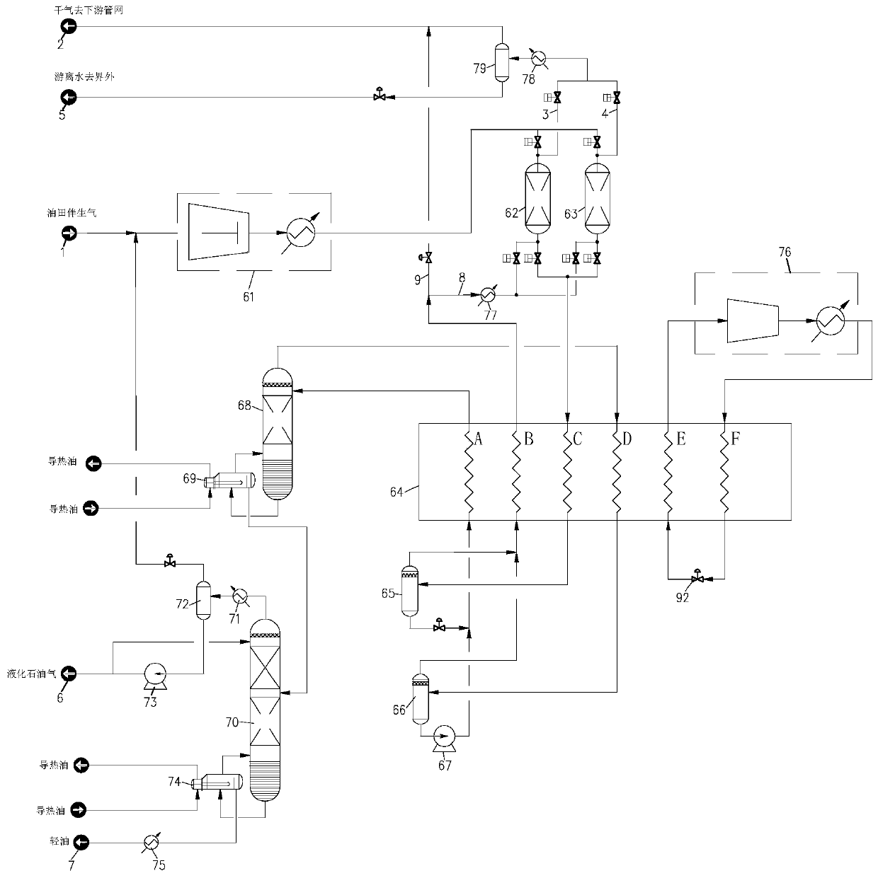
[0043] see figure 1 , this embodiment discloses a low-temperature flash light hydrocarbon recovery system for oilfield associated gas, including a feed gas compressor 61, No. 1 adsorption tower 62, No. 2 adsorption tower 63, low-temperature heat exchanger 64, a first-stage Flash separator 65 , secondary flash separator 66 , deethanizer 68 , deethanizer reboiler 69 , liquefied gas tower 70 , reflux tank 72 and liquefied gas tower reboiler 74 .

[0044] In this embodiment, the low-temperature heat exchanger 64 is an aluminum plate-fin heat exchanger, and channels A, B, C, D, E and F are arranged inside. The cooling capacity of the low-temperature heat exchanger 64 is provided by a mixed refrigerant...


PUM


Abstract

The invention relates to a low-temperature flash evaporation and light hydrocarbon recovery system and method used for oilfield associated gas. The recovery system comprises a raw material gas compressor, a first adsorption column, a low-temperature heat exchanger, a first-stage flash separator, a second-stage flash separator, a dethanizing column, a dethanizing column reboiler, a liquefied gas column, a reflux drum and a liquefied gas column reboiler; and a channel A, a channel B, a channel C and a channel D are arranged in the low-temperature heat exchanger. In the low-temperature flash evaporation and light hydrocarbon recovery system used for the oilfield associated gas, gas from the top of the dethanizing column enters the second-stage flash separator after running through the low-temperature heat exchanger again and being cooled to certain temperature, separated gas meets the requirements of dry gas exportation, after the separated gas and gas separated from the first-stage flashseparator are mixed, and are reheated by the low-temperature heat exchanger, obtained mixed gas goes to a dry gas downstream pipe network, liquid separated from the second-stage flash separator is boosted by a liquid booster pump, then obtained boosted liquid and liquid separated from the first-stage flash separator are mixed, and obtained mixed liquid goes to the dethanizing column after being reheated by the low-temperature heat exchanger, so that the recovery rates of heavy components of propane, butane, pentane and the like are improved.

Description

technical field [0001] The invention relates to the technical field of oilfield associated gas treatment, in particular to a low-temperature flash light hydrocarbon recovery system and method for oilfield associated gas. Background technique [0002] As an available resource, oilfield associated gas refers to the gas that appears with petroleum liquids between oil layers during the production of oilfields. The main component is methane, which usually contains a large amount of ethane and heavy hydrocarbon components. Oilfield associated gas recovery and treatment refers to the separation of heavy components such as propane, butane, and pentane in the gas, and sales as liquefied petroleum gas (LPG), light oil, and other products. [0003] At present, due to the constraints of technical means and the relative difficulty in controlling the associated gas in the oilfield exploitation process, a large part of the associated gas in the oilfield is evacuated or burned, which does n...

Claims


Application Information

Patent Timeline
Patent Type & Authority Applications(China)
IPC IPC(8): B01D3/06B01D3/14B01D53/04B01D53/26C10L3/12
CPCB01D3/06B01D53/04B01D53/261C10L3/12B01D3/14B01D2259/40088
Inventor 范庆虎王庭宁周洪达
Owner HANGZHOU HONGSHENG ZHONGHONG NEW ENERGY CO LTD
Learn More