
A large-scale converter injection process method

A technology of large-scale converters and process methods, applied in the manufacture of converters, lime production, etc., can solve the problems of not considering the influence of stirring intensity on the smelting process, the single converter smelting process, and not considering the energy-saving and efficiency-enhancing issues, etc., to achieve the suppression of explosive Effects of splashing, reducing splashing, and shortening smelting time

Active Publication Date: 2021-06-11
内蒙古察右前旗蒙发铁合金有限责任公司
View PDF5 Cites 0 Cited by
  • Summary
  • Abstract
  • Description
  • Claims
  • Application Information

AI Technical Summary

Problems solved by technology

However, this patent does not consider the issue of energy saving and efficiency enhancement. At the same time, the converter smelting process is single, and the influence of stirring intensity on the smelting process is not considered.

Method used

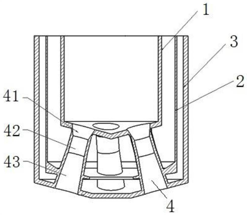
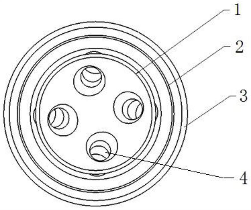
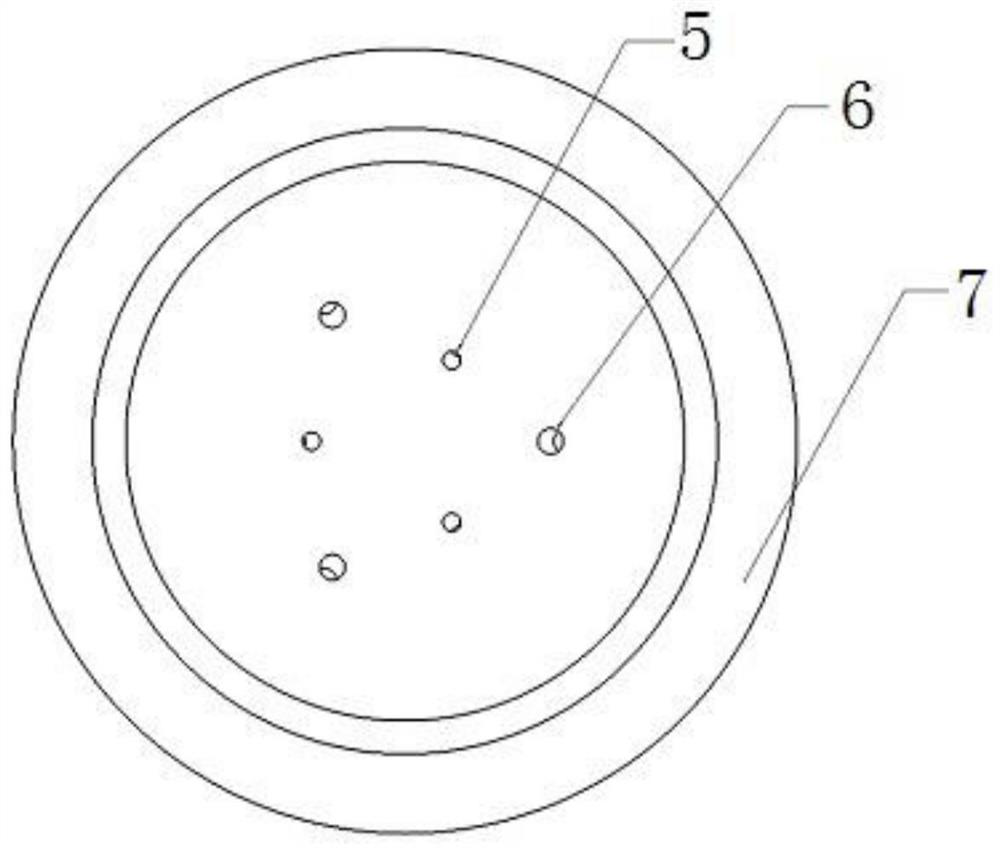

Image

  • A large-scale converter injection process method
  • A large-scale converter injection process method
  • A large-scale converter injection process method

Examples


Embodiment 1

[0065] In this embodiment, the main chemical composition of the smelted steel is as follows in weight percentage figure 1 Shown:

[0066] Table 1

[0067]

[0068] In this embodiment, when molten steel is smelted, solid particles are sprayed into the converter, and the requirements for solid particles are shown in Table 2:

[0069] Table 2

[0070] Types of solid particles Diameter before passivation diameter after passivation tolerance scope CaO particles 20nm--180nm ≤2mm ±5%

[0071] When CaO solid particles are sprayed into the converter, the medium gas is used as the carrier. The specific process steps are as follows:

[0072] 1) The tonnage of the converter project is 180t, which is suitable for converter smelting with a large scrap ratio.

[0073] 2) Simultaneously spray CaO solid particles through the swirl oxygen lance and the horizontal slot-type bottom blowing element, or use the horizontal slot-type bottom blowing element to blow...

Embodiment 2

[0083] In this embodiment, gas is blown into the converter through a swirl oxygen lance and a horizontal slot bottom blowing element.

[0084] The gas flow rate of the horizontal slot bottom blowing element is 710m 3 / h, bottom blowing intensity 0.06m 3 / min. t, the average carbon-oxygen product is 0.0021.

[0085] The inclination angle of the nozzle hole of the swirl oxygen lance is 7.5°, the swirl angle is 11°, and the inlet pressure of the oxygen lance is 1.0MPa. The diameter of the entrance of the nozzle shrinkage section is 80mm, the diameter of the throat is 40mm, and the impact area is increased by more than 4%.

[0086] After the oxygen blowing finishes, the swirl oxygen lance lifts the lance operation, stops blowing, calculates the amount of injecting rare earth element solid particles according to formula 2 (k=ay+bW), in the formula: injecting amount is y=6.93 tons, a =0.091, b=43%, w=0.03, k=0.64 tons. The solid particles of rare earth elements are sprayed thro...


PUM

PropertyMeasurementUnit
diameteraaaaaaaaaa
diameteraaaaaaaaaa
diameteraaaaaaaaaa

Abstract

The invention relates to a blowing process method of a large-scale converter. The converter is provided with a blowing system, and the blowing system includes a swirl oxygen lance arranged on the top of the converter and a horizontal slot type bottom blowing element arranged at the bottom of the converter; the swirl The flow oxygen lance and the horizontal slit bottom blowing element are used to inject gas or dispersed solid particles into the converter, and the solid particles include CaO solid particles or rare earth element solid particles; the gas injected by the swirl oxygen lance includes oxygen, Argon or nitrogen; the gas injected into the horizontal slit bottom blowing element includes CO2, argon, nitrogen or oxygen. The invention selectively blows air or solid particles into the converter through the swirling oxygen lance installed on the top of the converter and the horizontal slot bottom blowing element at the bottom of the converter, which is beneficial to reduce waste gas emission, reduce smelting time and improve the effect of slag removal. Reduce lime consumption.

Description

technical field [0001] The invention relates to the technical field of converter steelmaking, in particular to a large-scale converter blowing process method. Background technique [0002] The converter is mainly used for the smelting of carbon steel, alloy steel, copper and nickel. Converter steelmaking uses molten iron, scrap steel, and ferroalloy as the main raw materials. It does not rely on external energy, but relies on the physical heat of the molten iron itself and the chemical reaction between the components of the molten iron. Heat is generated to complete the steelmaking process in a converter. The blowing method of the converter is divided into top blowing, bottom blowing and side blowing according to the part where the gas is blown into the furnace; according to the type of gas injected, it is divided into air converter and oxygen converter. Basic oxygen top-blown and top-bottom compound-blown converters are currently the most commonly used steelmaking equipmen...

Claims


Application Information

Patent Timeline
Patent Type & Authority Patents(China)
IPC IPC(8): C21C5/35C21C5/46
CPCC21C5/35C21C5/4606Y02P40/40
Inventor 韩鹏刘坤王玺陈立峰王帅辉冯亮花刘广强
Owner 内蒙古察右前旗蒙发铁合金有限责任公司
Learn More