Photothermal conversion device based on hydrophilic carbon felt and application thereof

A light-to-heat conversion and hydrophilic technology, which can be applied to solar collectors in specific environments, solar collectors, and general water supply conservation. It can solve the problems of high cost, heat conduction loss, and poor evaporation effect, and achieve saturation The effect of high vapor pressure and high thermal efficiency

Active Publication Date: 2019-12-17
ZHEJIANG UNIV
View PDF8 Cites 6 Cited by
  • Summary
  • Abstract
  • Description
  • Claims
  • Application Information

AI Technical Summary

Problems solved by technology

However, the main obstacles to the application of this device are: (1) the lack of effective light-to-heat conversion materials as the top absorber
The reported photothermal conversion materials such as carbon nanotubes, graphene, semiconductor sulfides, noble metal materials, etc., have major problems in current research and future applications, such as complex preparation process, high cost, certain toxicity
And the temperature of the absor

Method used


Image

  • Photothermal conversion device based on hydrophilic carbon felt and application thereof
  • Photothermal conversion device based on hydrophilic carbon felt and application thereof

Examples


Embodiment 1

[0032] Embodiment 1—the surface hydrophilic treatment of carbon felt

[0033] The method for surface hydrophilic treatment of the commercialized carbon felt comprises the following steps: placing a commercialized carbon felt with an appropriate size in deionized water, cleaning it ultrasonically for 30 minutes, and then drying it for use. Place the above-mentioned carbon felt in a reaction vessel with an appropriate amount of mass concentration of 60% concentrated nitric acid solution (note: the carbon felt should be completely submerged in concentrated nitric acid), and then seal the reaction vessel. Heat in a water bath at 80°C for 2h to 6h. After cooling to room temperature, rinse the carbon felt with water repeatedly until neutral. Dry the above carbon felt in an oven at 60°C to obtain a hydrophilic carbon felt. By adjusting the heating time, carbon felts with different surface contact angles (60.1°-2.1°) can be obtained. Then cut according to the required size to obtain...

Embodiment 2

[0034] Embodiment 2—the surface hydrophilic treatment of carbon cloth

[0035] The method for surface hydrophilic treatment of commercialized carbon cloth comprises the following steps: arranging commercialized carbon with appropriate size in deionized water, ultrasonic cleaning for 30 minutes, and drying for later use. Arrange the above-mentioned carbon in the concentrated nitric acid solution with an appropriate mass concentration of 60% in the reaction vessel (note: the carbon cloth should be completely submerged in the concentrated nitric acid), and then seal the reaction vessel. Heat in a water bath at 80°C for 2h to 6h. After cooling to room temperature, rinse the carbon cloth with water repeatedly until it becomes neutral. Arrange the above carbon in an oven at 60°C for drying to obtain a hydrophilic carbon cloth. By adjusting the heating time, carbon cloths with different surface contact angles (74.1°-0.1°) can be obtained. Then it is cut according to the required si...

Embodiment 3

[0036] Example 3—Using hydrophilic carbon felt to construct light-to-heat conversion devices

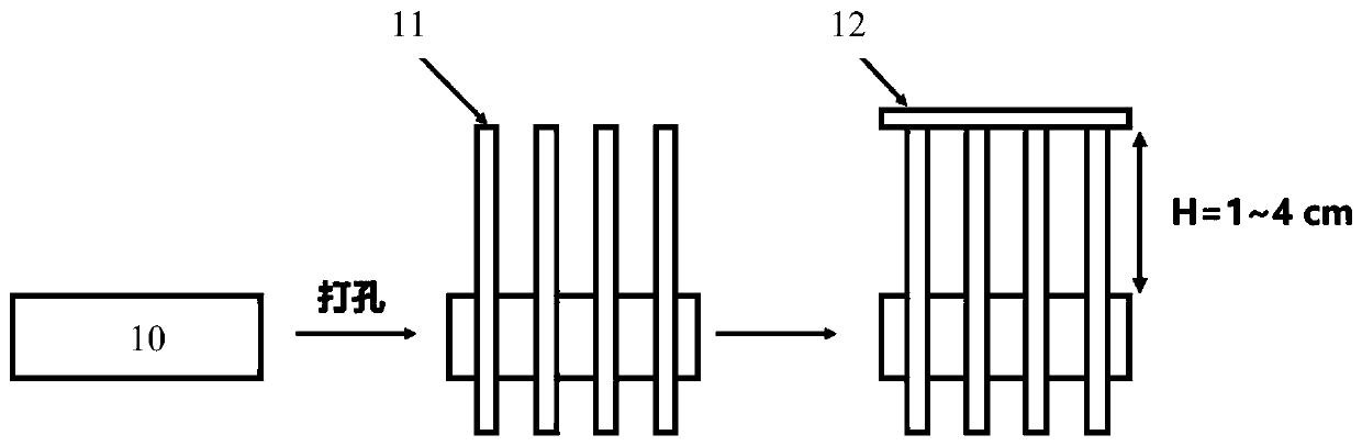
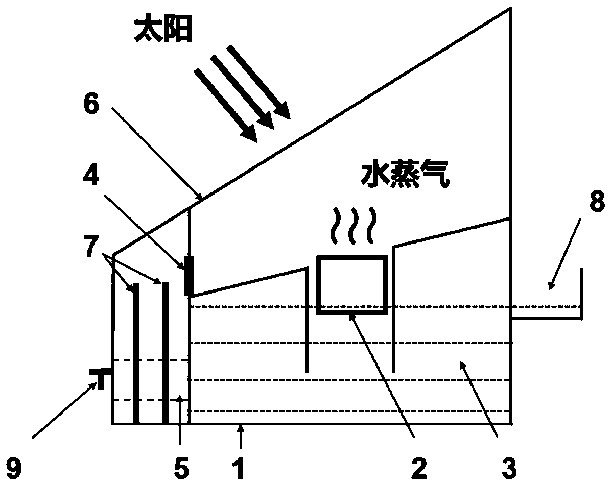
[0037]The method for constructing the light-to-heat conversion device 3 by using hydrophilic carbon felt, the specific steps are as follows: use a cylindrical polystyrene foam with a radius of 3.5 cm and a thickness of 1 cm as the heat insulating support 10, and evenly open 12 vertical cylinders Shaped channel (radius is consistent with the radius of water transmission body 11), as the support layer for the device to float on the surface of the liquid. The hydrophilic carbon felt or carbon cloth is rolled into a cylindrical hydrophilic carbon felt strip with a radius of 3 mm and a length of 3 cm to 7 cm, and then evenly inserted into the channels to form the water transport body 11 . Both ends of the water transport body 11 protrude from the upper and lower surfaces of the heat-insulating support 10, and the upper section is directly exposed to the air, and the length of the upper se...


PUM

PropertyMeasurementUnit
Radiusaaaaaaaaaa
Thicknessaaaaaaaaaa
Radiusaaaaaaaaaa

Abstract

The invention relates to the technical field of photothermal conversion, and aims to provide a photothermal conversion device based on hydrophilic carbon felt and application thereof. The photothermalconversion device comprises top absorbing bodies, middle water conveying bodies, and a bottom thermal insulation support body capable of floating on the surface of liquid; multiple vertical hole waysare formed in the thermal insulation support body at intervals; the water conveying bodies are inserted in the hole ways; the two ends of the water conveying bodies extend out of the upper and lowersurfaces of the thermal insulation support body, and the upper sections are directly exposed in air; and the top absorbing bodies are the flaky hydrophilic carbon felt, and are naturally placed at thetops of the water conveying bodies to realize supporting. The thermal insulation support body is higher in heat resistance, so that the downward transfer of heat absorbed by the top absorbing bodiesfrom sunlight is prevented, and the heat efficiency of the whole device is higher. The micro-nano hole ways at the upper sections of the water conveying bodies make direct contact with an air interface to achieve a higher saturated vapor pressure; water can cool the whole device during volatilizing; and the heat can be obtained from the environment to be nearer the thermodynamics evaporation limit.

Description

technical field [0001] The invention relates to the field of photothermal conversion, in particular to a photothermal conversion device based on hydrophilic carbon felt and its application. Background technique [0002] With the gradual shortage of fresh water resources and the increasingly serious water pollution, efficient, low-toxic, cheap, and environmentally friendly water treatment technologies are particularly critical. Solar water evaporation technology is favored by many scholars for its advantages of low energy consumption, no secondary pollution, and high purity of fresh water. However, traditional solar water evaporators generally rely on complex and huge light concentrating or light tracking devices. These devices are greatly affected by the weather, difficult to maintain in the later stage, high in cost, and large in heat loss, which is not conducive to large-scale industrialization. application. [0003] In order to improve the evaporation performance of the...

Claims


Application Information

Patent Timeline
IPC IPC(8): F24S20/00F24S80/00C02F1/14C02F1/40D06M11/64D04H1/08D06M101/40C02F103/08
CPCC02F1/14C02F1/40C02F2103/08D04H1/08D06M11/64D06M2101/40F24S20/00F24S80/00Y02A20/124Y02A20/142Y02A20/212Y02E10/40
Inventor 成少安于祯
Owner ZHEJIANG UNIV
Why Eureka
Try Eureka