
Fabrication method of surface relief grating structure

A grating structure and manufacturing method technology, applied in the direction of diffraction grating, optics, optical elements, etc., can solve the problems that laser direct writing cannot accurately control the contour depth, contour depth error, low work efficiency, etc., and achieve precise control of substrate etching depth , widely used, and the effect of simplifying the production process

Active Publication Date: 2021-02-19
AAC OPTICS (CHANGZHOU) CO LTD
View PDF5 Cites 0 Cited by
  • Summary
  • Abstract
  • Description
  • Claims
  • Application Information

AI Technical Summary

Problems solved by technology

[0005] But the biggest problem with laser direct writing is that it cannot precisely control the contour depth
The processed contour depth is related to many factors such as exposure intensity, scanning speed, resist material, developing formula, ambient temperature and developing temperature. Constant working conditions to control depth error, low working efficiency and low controllability

Method used


Image

  • Fabrication method of surface relief grating structure
  • Fabrication method of surface relief grating structure
  • Fabrication method of surface relief grating structure

Examples


Embodiment Construction

[0039] The present invention will be further described below in conjunction with the accompanying drawings and embodiments.

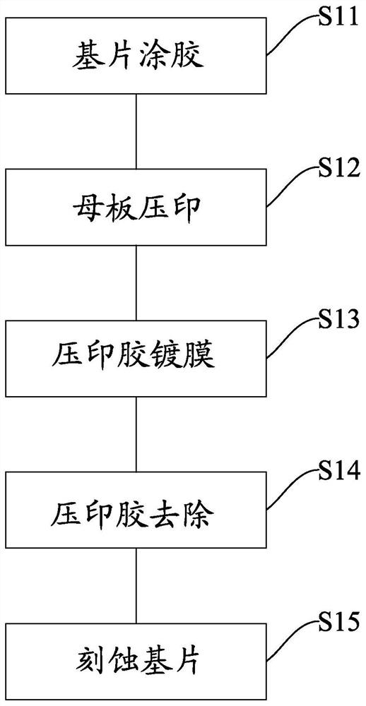
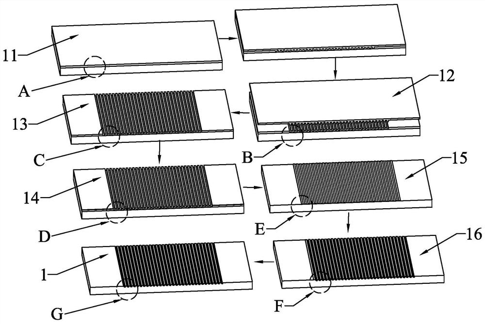
[0040] see Figure 1-2 , the invention discloses a method for manufacturing a surface relief grating structure, comprising the following steps:

[0041] Before coating the embossing adhesive layer, the substrate needs to be placed in cleaning equipment, soaked in absolute ethanol and acetone to remove residual organic matter, and then rinsed and dried with a large amount of deionized water; the material of the substrate is generally Glass material.

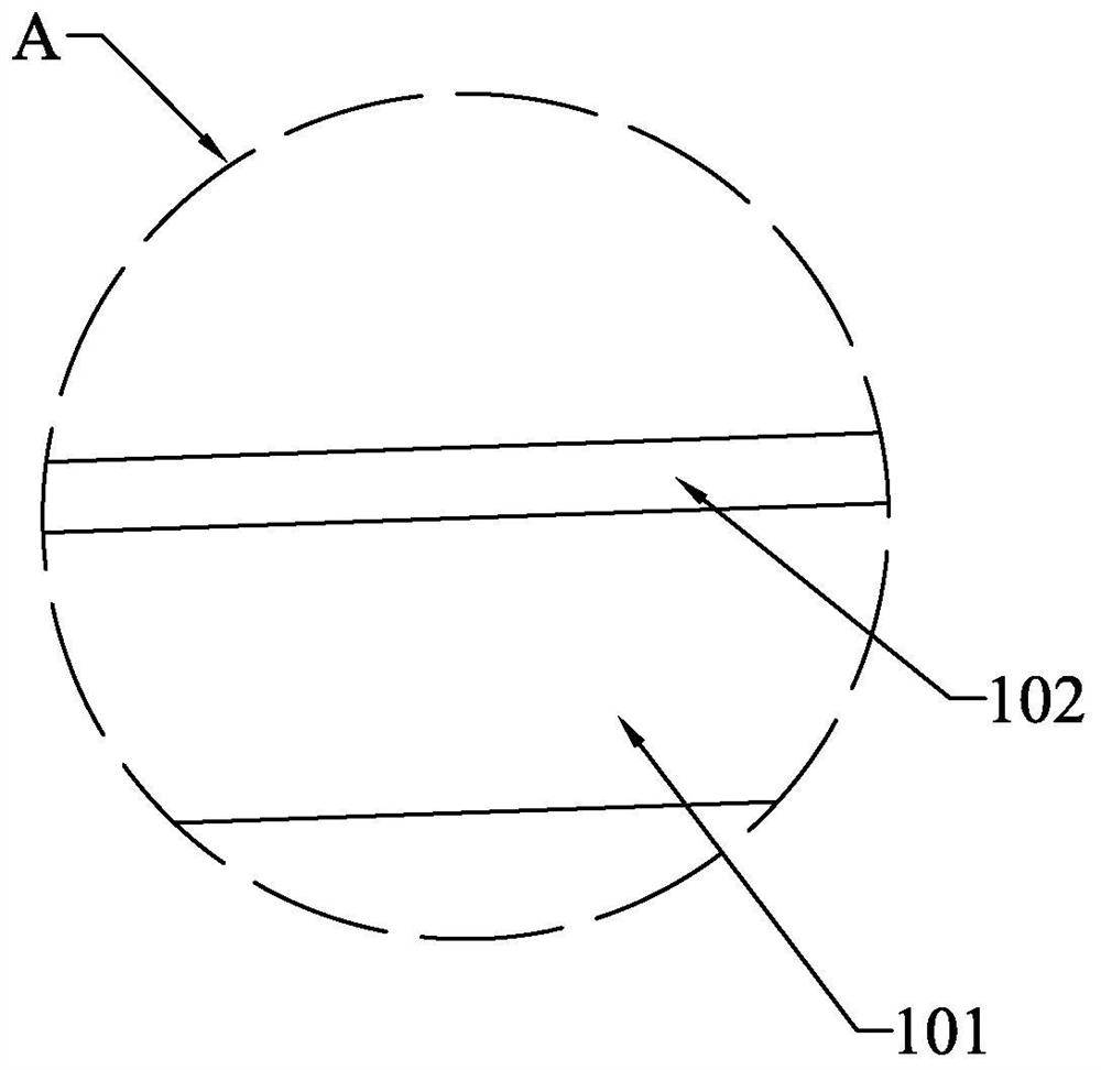
[0042] S1, substrate coating: please refer to further image 3 , providing the substrate 101 for making the grating structure, coating the embossing glue layer 102 on the surface of the substrate 101 to obtain the substrate 11; coating a layer of embossing glue on the substrate 101, when the glue concentration and the spin coating rate are different When the time changes, the thickness of a single spin c...


PUM

PropertyMeasurementUnit
widthaaaaaaaaaa

Abstract

The invention provides a method for manufacturing a surface relief grating structure. The method includes the processes of substrate coating, mother board imprinting, embossing adhesive coating, embossing adhesive removal, and substrate etching. The second grating structure is obtained by directly embossing the first grating structure on the mother board, avoiding the The process of exposure and development in the manufacturing process of the grating structure simplifies the production process of the grating structure; one motherboard can produce multiple daughter boards successively, and multiple motherboards can produce multiple daughter boards at the same time, which can realize the mass production process of the grating structure. The embossing glue coating process is added, and the first metal film whose etching rate is different from that of the substrate is selected. During the substrate etching process, the power of the ion beam can be controlled to achieve the effect of accurately controlling the etching depth of the substrate; at the same time, the ion beam The included angle between the emission line and the substrate surface is not a right angle, so that the etched groove surface forms an inclined groove surface, so as to obtain a target grating structure in which the substrate surface forms trapezoidal slits.

Description

【Technical field】 [0001] The invention relates to the field of grating production, in particular to a method for making a surface relief grating structure. 【Background technique】 [0002] Gratings are important components of various spectral analysis instruments, and are increasingly used in emerging fields such as metrology, imaging, information processing, inherited optics, and optical communications. In recent years, with the rapid development of semiconductor technology, a new type of optical application products has also developed, which is AR (Augmented Reality) products. AR is an augmentation of reality, a fusion of virtual images and real images. At present, head-mounted AR devices on the market mostly use the principle of optical projection, that is, the fusion of real scenes and virtual scenes is realized through lenses installed in front of the eyes. Among them, the Hololens product launched by Microsoft is currently on the market and has the best experience. I...

Claims


Application Information

Patent Timeline
Patent Type & Authority Patents(China)
IPC IPC(8): G02B5/18
CPCG02B5/1852G02B5/1857
Inventor 王晶
Owner AAC OPTICS (CHANGZHOU) CO LTD
Learn More