Hot-blast stove high-temperature waste gas recycling method

A technology of high-temperature exhaust gas and hot blast stove, which is applied in the field of ironmaking, which can solve the problems of energy waste, increased gas consumption, and short downtime, and achieve the effects of good operation stability, less gas consumption, and reduced emissions

Inactive Publication Date: 2019-12-27
YUNNAN DESHENG STEEL CO LTD
View PDF6 Cites 0 Cited by
  • Summary
  • Abstract
  • Description
  • Claims
  • Application Information

AI Technical Summary

Problems solved by technology

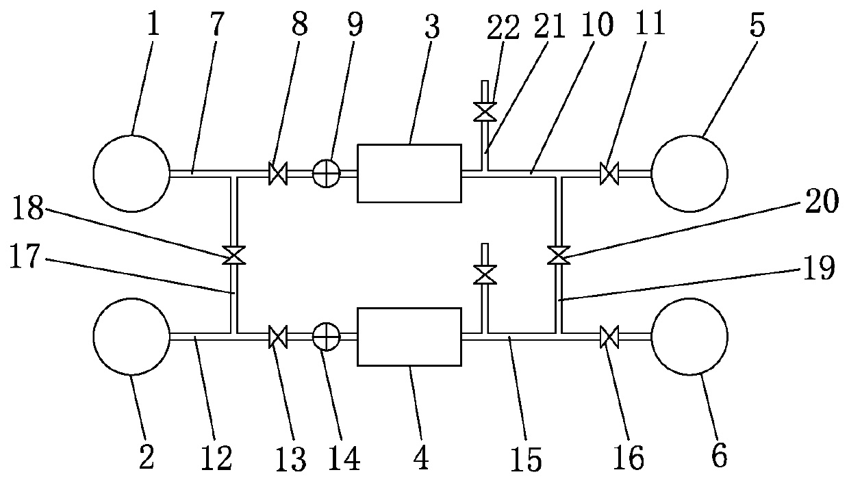
[0002] The process of using high-temperature exhaust gas to mix air when firing the flue gas furnace is to recycle and reuse the exhaust gas of the hot blast stove. The service life of the furnace bell mouth and furnace has a certain extension effect. The existing technology can only realize that the high-temperature exhaust gas of one hot blast stove can only be used by one flue gas stove, and the high-temperature exhaust gas of the other hot blast stove can only be used by another flue gas. There are some deficiencies in this one-to-one utilization method, mainly: low recycling rate of high-temperature waste gas from hot blast stoves, increased gas consumption, increased energy consumption, and environmental pollution. For example, when the first hot blast stove 1 During major and medium repairs, the hot blast stove is shut down and there is no high-temperature exhaust gas. The corresponding dry gas produced by the first flue gas stove 3 is completely generated by gas combustion, and the amount of gas consumption increases, and the energy consumption increases. At this time, the second hot blast furnace The high-temperature exhaust gas of furnace 2 is in a state of oversupply, and the corresponding exhaust gas exhausted by the second flue gas furnace 4 is discharged from the chimney of the hot blast furnace to the air, which causes a certain amount of energy waste and increases the ambient temperature of the area. In addition, I The factory currently has 2 sets of EM53-575 medium-speed ball mills. Each mill is stopped once a week for regular inspection and maintenance, each time for 8 hours, and the annual shutdown is 864 hours. 2.5 hours of shutdown every hour, 2700 hours of shutdown per year, and 96 hours of rotation and shutdown of 2 mills per year for annual regular inspection and maintenance. In the above cases, in order to meet production needs, one mill must be guaranteed to work normally. The downtime is short, and if the flue gas furnace must be stopped every time it is shut down, it will have many unfavorable factors for production and safety. After the gas furnace is shut down, it takes a long time from the successful ignition to the furnace temperature, bell mouth temperature, and mill inlet temperature to meet the safety requirements of the mill, and it is not suitable for regulation. Therefore, in order to ensure production and safety, the mill has been stopped for a short time. The operating mode of the flue gas furnace is that the flue gas furnace is stopped when the machine is shut down. For example, the first mill 5 is shut down, and the first flue gas furnace 3 is not turned on. Just open the air-releasing butterfly valve 22 to release the high temperature generated. The dry gas is naturally discharged to the air. The problems of this operation method are: first, the dry gas produced by a single flue gas furnace can only be used for the production of the corresponding mill, and it can only be released when the mill is not in use, resulting in the loss of blast furnace gas. Waste; the second is to discharge high-temperature dry gas to the air, which has an impact on the environment. At the same time, the dry gas contains incompletely combusted CO, which threatens the safety of personnel within a certain range of the vent. Therefore, it is necessary to improve the existing technology to solve the problem. above question

Method used


Image

  • Hot-blast stove high-temperature waste gas recycling method

Examples


Embodiment Construction

[0019] The following will clearly and completely describe the technical solutions in the embodiments of the present invention with reference to the accompanying drawings in the embodiments of the present invention. Obviously, the described embodiments are only some, not all, embodiments of the present invention. Based on the embodiments of the present invention, all other embodiments obtained by persons of ordinary skill in the art without making creative efforts belong to the protection scope of the present invention.

[0020] see figure 1 , an embodiment provided by the present invention: a method for recycling high-temperature exhaust gas from a hot blast stove, the method includes the following steps:

[0021] S1: During the overhaul period of the first hot blast stove 1, the first hot blast stove 1 is shut down, and no high-temperature exhaust gas is discharged from the first high-temperature exhaust gas pipeline 7. At this time, the first public regulating valve 18 is op...


PUM


Abstract

The invention discloses a hot-blast stove high-temperature waste gas recycling method. The method comprises the following steps that when a first hot-blast stove is in overhaul and medium repair periods, the first hot-blast stove is shut down, no high-temperature waste gas is discharged from a first high-temperature waste gas pipeline, at the moment, a first common regulating valve is opened, a first high-temperature induced draft fan is started, a first flue gas furnace inlet regulating valve is opened, so that a part of high-temperature waste gas generated by a second hot-blast stove passesthrough a first common pipeline and enters a mixing chamber of a first flue gas furnace under the air draft action of the first high-temperature induced draft fan. According to the method, by arranging the first common pipeline, the first common regulating valve, a second common pipeline and a second common regulating valve, high-temperature waste gas of the hot-blast stove and high-temperature drying gas of the flue gas furnace are further recycled, the waste gas utilization rate of the hot-blast stove is improved, the temperature control performance of a furnace hearth of the flue gas furnace is improved, the use amount of blast furnace gas is saved, the high-temperature waste gas and the drying gas which are diffused into air is reduced, and the harm of toxic and harmful substances in the diffused waste gas to the surrounding environment and personal safety is reduced.

Description

technical field [0001] The invention relates to the technical field of ironmaking, in particular to a method for recycling high-temperature exhaust gas from a hot blast stove. Background technique [0002] The process of using high-temperature exhaust gas to mix air when firing the flue gas furnace is to recycle and reuse the exhaust gas of the hot blast stove. The service life of the furnace bell mouth and furnace has a certain extension effect. The existing technology can only realize that the high-temperature exhaust gas of one hot blast stove can only be used by one flue gas stove, and the high-temperature exhaust gas of the other hot blast stove can only be used by another flue gas. There are some deficiencies in this one-to-one utilization method, mainly: low recycling rate of high-temperature waste gas from hot blast stoves, increased gas consumption, increased energy consumption, and environmental pollution. For example, when the first hot blast stove 1 During major...

Claims


Application Information

Patent Timeline
Patent Type & Authority Applications(China)
IPC IPC(8): F27D17/00F24H3/02F24H9/12F24H9/20
CPCF24H3/02F24H9/12F24H9/2064F27D17/001F27D17/004
Inventor 江海燕李贵国唐田李华国华毕祥速亮李华陶明华李家富刘红忠李文和张举学
Owner YUNNAN DESHENG STEEL CO LTD
Why Eureka
Try Eureka