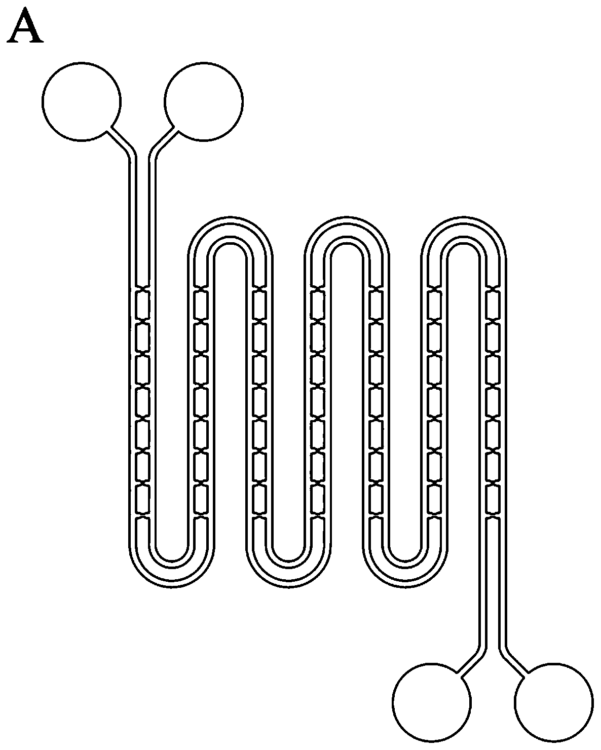
Microfluidic chip and design method and application thereof
A microfluidic chip and fluid technology, applied in biochemical equipment and methods, methods for stress-stimulated microbial growth, chemical instruments and methods, etc., to achieve the effects of good biocompatibility, easy operation, and high capture efficiency
- Summary
- Abstract
- Description
- Claims
- Application Information
AI Technical Summary
Problems solved by technology
Method used
Image
Examples
Embodiment 1
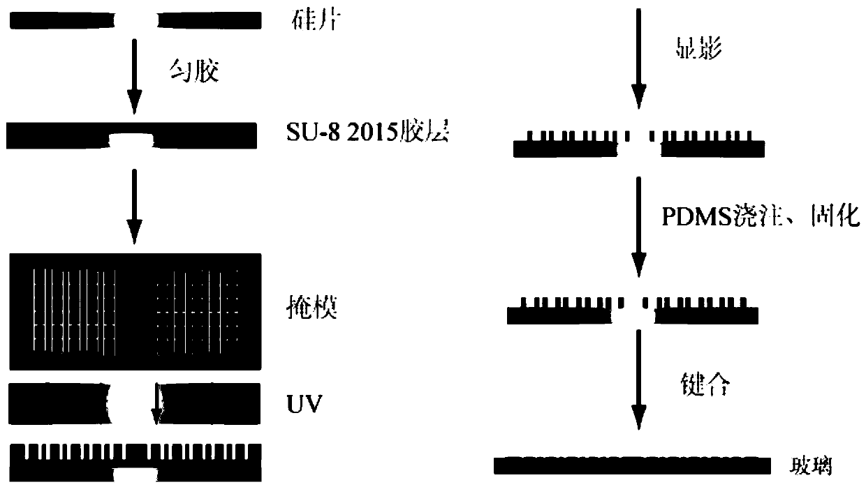
[0049] Such as figure 1 , the fabrication of the microfluidic chip in this embodiment adopts the soft lithography method, including the following steps:
[0050] Mold production: heat the silicon wafer in the water tiger acid solution to boiling for 30 minutes, wash it with ultrapure water, and blow it dry with nitrogen gas. 65, baked for 10 minutes, 95m for 4 minutes, exposed 3 times with a UV exposure machine, each time for 30s, and dried with nitrogen after development, and the pattern of cell capture was obtained on the silicon wafer.
[0051] Chip production: Add trifluoro(1H, 1H, 2H, 2H perfluorooctyl) silane and mold in a dry vessel, keep the vacuum for 2 hours to make the surface of the mold hydrophobic, polydimethylsiloxane (PDMS) prepolymer Mix with the initiator at a mass ratio of 10:1 and pour into the mold, and place it at 75 for 2 hours after removing air bubbles. The polymerized PDMS sheet is peeled off, cut into shape, punched with a flat syringe needle, and ...
Embodiment 2~4
[0057] The method for designing the size of each part of the microfluidic chip includes the following steps:
[0058] 1) Utilizing the principle of “the least path of flow resistance”, the flow of fluid in the channel usually occurs at a low Reynolds coefficient (Re). For laminar flow in a rectangular channel without drop and obstacles, the resistance calculation formula is
[0059]
[0060] Among them, μ is the viscosity of the fluid, Q is the flow rate, Q=V×A, V is the flow velocity, A is the cross-sectional area of the channel, L, w, h are the length, width and height of the channel respectively, and α is related to the aspect ratio The dimensionless parameter of ,
[0061]
[0062]
[0063] 2) Calculate the pressure drop △P:
[0064] For the resistance of the capture unit, it is approximated as a rectangular resistance;
[0065] The pressure drop of the fluid through the first main channel and the narrow channel, where P 0 Indicates narrow channel, P 1 Indic...
Embodiment 5~8
[0080] Water is used as the simulated material, the length of the main channel between the capture units is 150 μm, the width and length of the entrance of the capture unit remain unchanged, and the shape of the capture unit is changed. The shapes of the capture units in Examples 3 to 8 are triangle, semi-ellipse, square and circle respectively .
[0081] Such as Figure 5 As shown, the four shapes of the capture unit have no effect on the flow resistance, but the fluid flow lines passing through the capture unit are different. When the capture unit is triangular and semi-elliptical, the fluid is more aggregated, which can reduce the accumulation of cells in the capture unit. Cells occupy a larger area ratio. The circle and rectangle have more nonlinear fluid in the capture unit, and the pressure diagram shows that the circle and rectangle are more likely to generate shear force at the connection between the main channel and the capture unit.
[0082] 1. Single-cell capture ...
PUM
| Property | Measurement | Unit |
|---|---|---|
| Length | aaaaa | aaaaa |
Abstract
Description
Claims
Application Information
 - R&D
- Intellectual Property
- Life Sciences
- Materials
- Tech Scout
- Unparalleled Data Quality
- Higher Quality Content
- 60% Fewer Hallucinations
Browse by: Latest US Patents, China's latest patents, Technical Efficacy Thesaurus, Application Domain, Technology Topic, Popular Technical Reports.
© 2025 PatSnap. All rights reserved.Legal|Privacy policy|Modern Slavery Act Transparency Statement|Sitemap|About US| Contact US: help@patsnap.com


