Modified silicate grounding module and manufacturing method and manufacturing mold thereof

A technology of Portland and Portland cement, applied in the direction of manufacturing tools, contact parts, connecting contact materials, etc., can solve the problem of insufficient contact between metal materials and soil, inadequate anti-corrosion measures for welding parts, and accelerated internal metal materials. Corrosion and other problems, to achieve superior thermal stability, save manpower and material resources, and increase corrosion resistance

Inactive Publication Date: 2020-01-07
CHINA ELECTRIC POWER RES INST +4
View PDF9 Cites 0 Cited by
  • Summary
  • Abstract
  • Description
  • Claims
  • Application Information

AI Technical Summary

Problems solved by technology

Since the metal grounding material is not homogeneous with the soil, the contact between the metal material and the soil is not dense after construction, and the contact resistance is large. In some places with high soil resistivity or inconvenient construction, it is difficult to achieve it with only traditional metal grounding materials. Requirements, not only the laying length needs to be lengthened, the construction excavation volume is large, but resistance-reducing materials need to be laid to meet the grounding resistance requirements
In addition, the biggest bottleneck problem of metal grounding materials is the corrosion of grounding materials. Even if stainless steel or copper-clad steel and other metal materials with anti-corrosion measures are used, due to wear during transportation or construction, the anti-corrosion measures for welding parts are not in place. There will be pitting corrosion, etc.
When using resistance-reducing materials to assist in reducing resistance, the corrosion of internal metal materials will be accelerated. The resistance-reducing effect is good in the first few years after the completion of the project. Afterwards, due to the accelerated corrosion, the grounding resistance will gradually increase, and the grounding effect will become worse and worse.

Method used


Image

  • Modified silicate grounding module and manufacturing method and manufacturing mold thereof
  • Modified silicate grounding module and manufacturing method and manufacturing mold thereof
  • Modified silicate grounding module and manufacturing method and manufacturing mold thereof

Examples


Embodiment 1

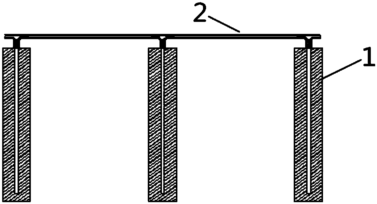
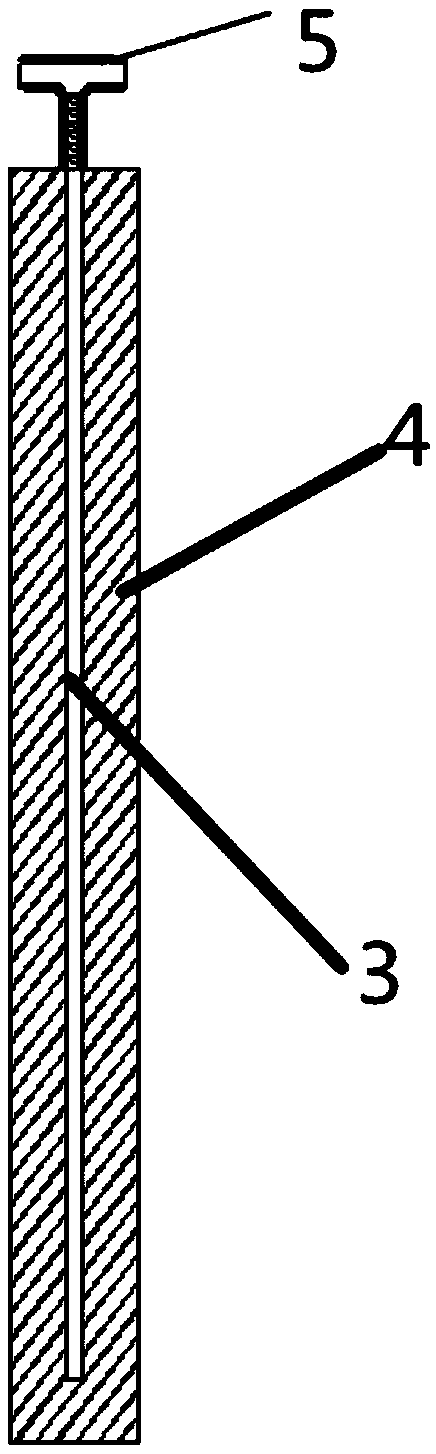
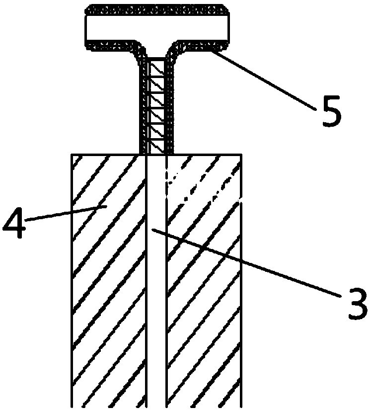
[0049] Such as Figure 1 to Figure 5 As shown, the present invention provides a modified silicate grounding module, which includes a grounding module 1 sequentially connected by a connecting wire 2; the module 1 includes a metal core material 3 and covers the metal core The modified silicate composite layer 4 of the material 3; the upper end of the metal core 3 penetrates the modified silicate composite layer 4 and is connected to the connection wire 2 through a connecting piece.

[0050] The modified silicate composite layer 4 includes the following components by mass fraction:

[0051] Portland cement: 20%, bentonite: 15%, graphite: 5%, nano-carbon fiber 5%, stainless steel fiber: 10% and polyacrylamide 5%.

[0052] The modified silicate composite layer 4 is columnar, and its cross-section is square.

[0053] The metal core material 3 is columnar, and the ratio of the cross-sectional area of ​​the metal core material 3 to the cross-sectional area of ​​the modified silicate c...

Embodiment 2

[0058] The structure of this embodiment is basically the same as that of Embodiment 1, except that the composition ratio of the modified silicate composite layer 4, the cross-sectional area of ​​the metal core material 3 and the composite of the modified silicate The ratio of the cross-sectional area of ​​layer 4 and the angle between adjacent connecting lines 2:

[0059] The modified silicate composite layer 4 includes the following components by mass fraction:

[0060] Portland cement: 35%, bentonite: 20%, graphite: 10%, nano-carbon fiber 1%, stainless steel fiber: 5% and polyacrylamide 1%.

[0061] The metal core material 3 is columnar, and the ratio of the cross-sectional area of ​​the metal core material 3 to the cross-sectional area of ​​the modified silicate composite layer 4 is 1:15.

[0062] The included angle between adjacent connecting lines 2 is 180°.

Embodiment 3

[0064] The structure of this embodiment is basically the same as that of Embodiment 1, except that the composition ratio of the modified silicate composite layer 4, the cross-sectional area of ​​the metal core material 3 and the composite of the modified silicate The ratio of the cross-sectional area of ​​layer 4 and the angle between adjacent connecting lines 2:

[0065] The modified silicate composite layer 4 includes the following components by mass fraction:

[0066] Portland cement: 25%, bentonite: 17%, graphite: 7%, nano-carbon fiber 2%, stainless steel fiber: 6% and polyacrylamide 2%.

[0067] The metal core material 3 is columnar, and the ratio of the cross-sectional area of ​​the metal core material 3 to the cross-sectional area of ​​the modified silicate composite layer 4 is 1:20.

[0068] The included angle between adjacent connecting lines 2 is 120°.


PUM


Abstract

The invention provides a modified silicate grounding module group and a manufacturing method and a manufacturing mold thereof. The module group comprises grounding modules which are sequentially connected through connecting wires, wherein each module comprises a metal core material and a modified silicate composite layer coating the metal core material, and the upper end of the metal core materialpenetrates through the modified silicate composite layer and is connected with the connecting wire through a connecting piece. According to the technical scheme provided by the invention, the grounding modules formed by the metal core material and the composite layer are sequentially connected to form the grounding module group; the hygroscopicity and adhesiveness of the composite layer are better than those of metal, and the compactness of the composite layer bonded with soil is better than that of the metal, so that the contact resistance between the grounding module group and the soil andthe grounding resistance of the grounding module group are reduced; and the composite material can play a role in protecting the metal, so that the corrosion of the metal is avoided, the corrosion resistance of the whole grounding module group is improved, and the service life of the grounding module group is greatly prolonged.

Description

technical field [0001] The invention relates to a grounding module, in particular to a modified silicate grounding module, a manufacturing method thereof and a manufacturing mold. Background technique [0002] With the development of science and technology, the demand for electricity in the society is increasing and the requirements are getting higher and higher. While electricity brings great convenience to human beings, people pay more and more attention to its safety. Lightning is an important factor that seriously threatens the safe and reliable operation of the power system. It can easily cause the tripping of transmission lines, which will bring huge economic losses to the society. Therefore, people have been vigorously studying the method of improving lightning tripping of transmission lines, and effectively reducing the grounding resistance of towers has been proved to be a measure with the best effect and the highest feasibility. [0003] The grounding of power tra...

Claims


Application Information

Patent Timeline
Patent Type & Authority Applications(China)
IPC IPC(8): H01R13/03H01R4/66H01R4/58B28B23/00C04B28/04B28B7/24B28B1/14
CPCB28B1/14B28B7/24B28B23/00C04B28/04H01R4/58H01R4/66H01R13/03C04B14/104C04B14/024C04B14/386C04B14/48C04B24/2652
Inventor 黄彭李文杰林立鹏周鑫崔荣坤刘蕊莫娟房正刚李彦霖王炜
Owner CHINA ELECTRIC POWER RES INST
Why Eureka
Try Eureka