

Turbine blade air film hole precision forming method
A turbine blade and precision forming technology, applied in chemical instruments and methods, self-solidification method, casting mold composition, etc., can solve the problems of uncontrollable machining dimensional accuracy, inability to process special-shaped holes and multi-angle inclined holes, and low machining efficiency. , to reduce the recast layer and micro-cracks, speed up the rapid research and development, and eliminate the positioning error.
- Summary
- Abstract
- Description
- Claims
- Application Information
AI Technical Summary
Problems solved by technology
Method used
Image

Examples
Embodiment 1
[0029] For the precision forming method of the air film hole of the turbine blade, the steps are as follows:
[0030] 1) Manufacture of turbine blade resin mold
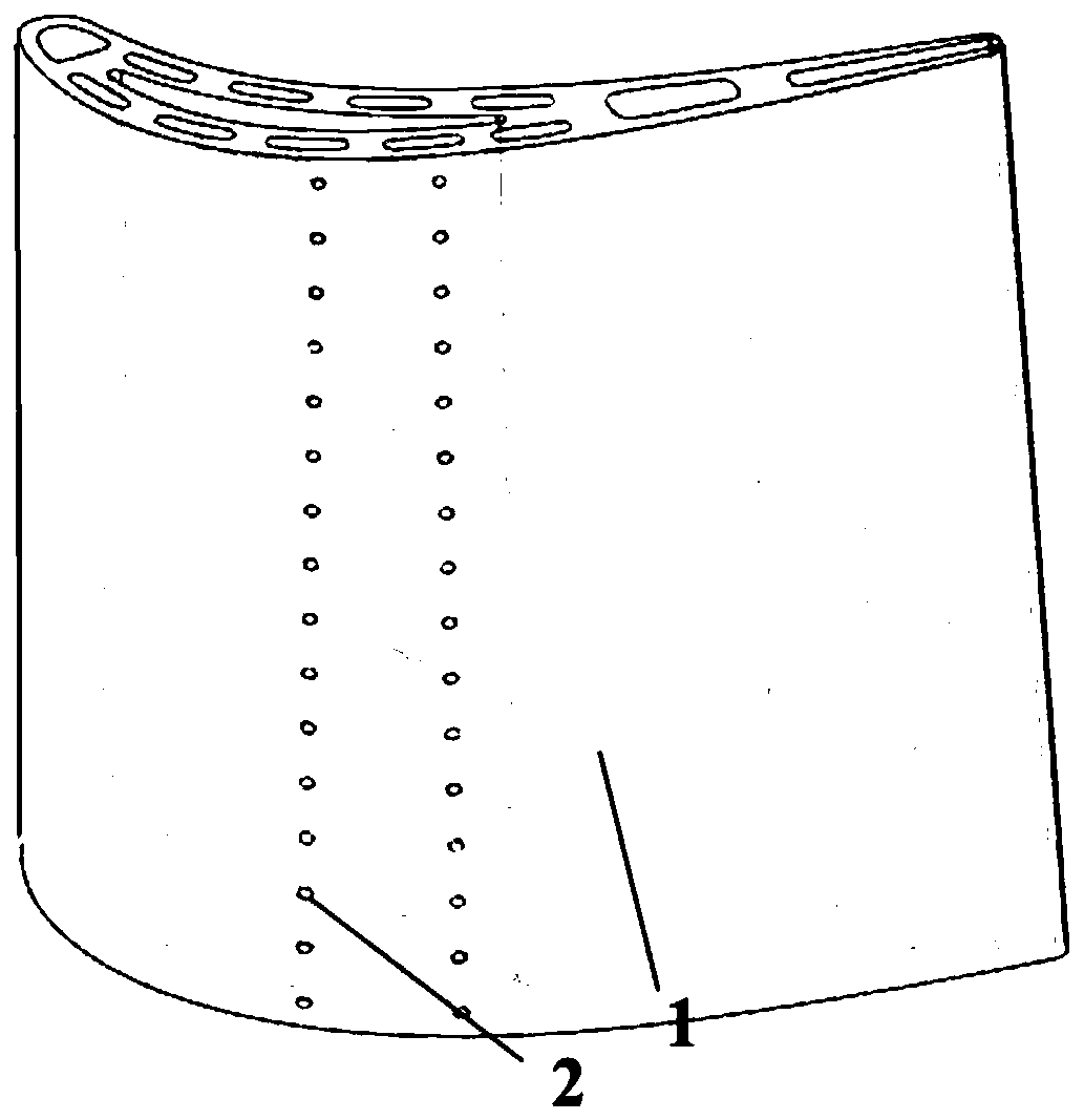
[0031] The present invention utilizes light-curing rapid prototyping technology to manufacture resin molds. First, a resin mold CAD model is designed using commercial three-dimensional software, and a two-dimensional slice file with a layered thickness of 0.07mm is generated, and the resin mold is quickly and automatically manufactured under the control of the slice file. For stereolithography prototypes, see figure 1 , where 1 is the blade body, and 2 is the air film hole structure. The manufactured turbine blade resin mold has high precision, high rigidity, and good surface quality, and can be used as a molding mold for ceramic ligands.
[0032] 2) Prepare ceramic slurry
[0033] First, dissolve the organic matter in deionized water, add dispersant, uniformly mixed alumina ceramic powder and mineralizer powder i...
PUM
 Abstract
Description
Claims
Application Information