Gasification pyrolysis system for recycling flue gas and application of gasification pyrolysis system

A pyrolysis and flue gas technology, applied in the field of pyrolysis system and gasification pyrolysis system, can solve the problem of low temperature of flue gas, and achieve the effect of improving economic benefits, improving heat exchange efficiency and improving pyrolysis effect

Pending Publication Date: 2020-02-04
上海和惠生态环境科技有限公司
View PDF4 Cites 2 Cited by
  • Summary
  • Abstract
  • Description
  • Claims
  • Application Information

AI Technical Summary

Problems solved by technology

However, the device for dewhitening flue gas by the condensation method has a low ability to reduce the temperature of the flue gas, and can only reduce the temperature of the flue gas by 5-10°C. When the flue gas is discharged into the chimney, there will still be a large amount of white smoke.

Method used


Image

  • Gasification pyrolysis system for recycling flue gas and application of gasification pyrolysis system
  • Gasification pyrolysis system for recycling flue gas and application of gasification pyrolysis system

Examples


Embodiment 1

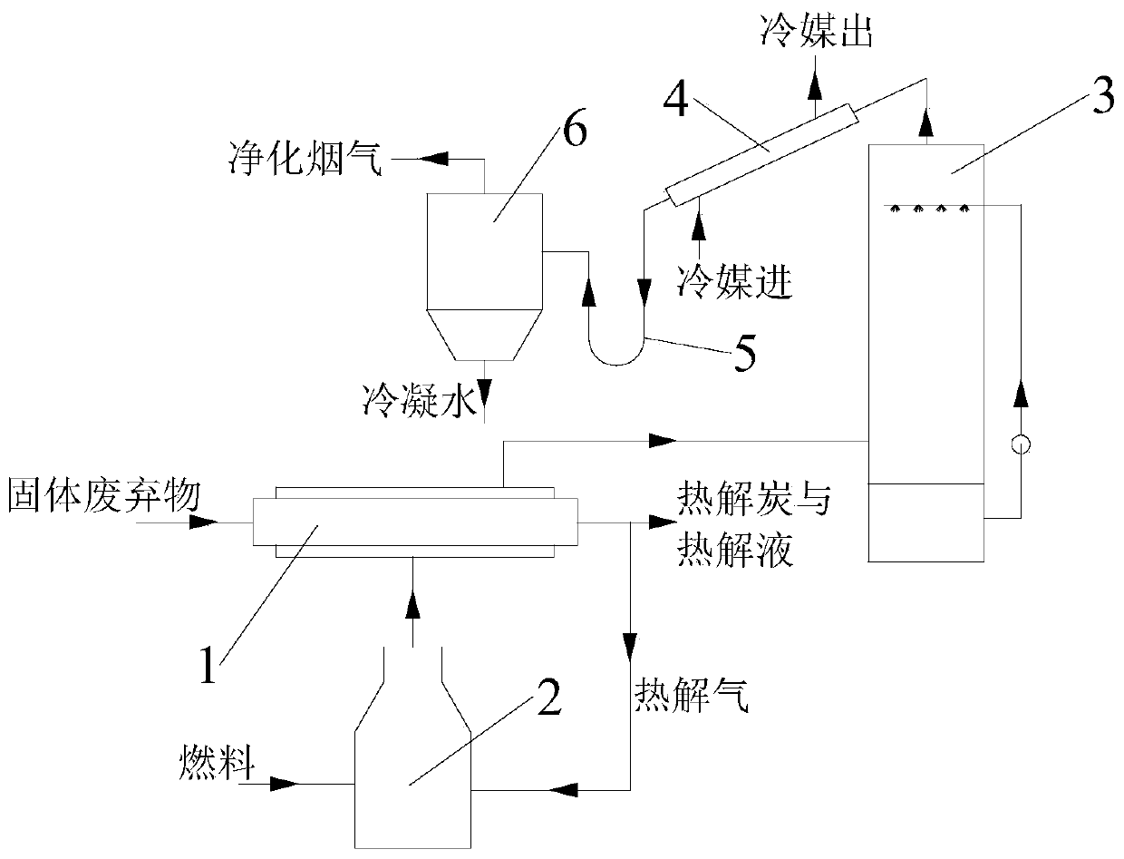
[0054] This embodiment provides a gasification and pyrolysis system for recycling flue gas, the structural schematic diagram of the gasification and pyrolysis system for recycling flue gas is as follows figure 1 As shown, it includes a pyrolysis unit, an absorption tower 3 and a condensation unit connected in sequence.

[0055] Described pyrolysis unit comprises pyrolysis furnace 1 and combustion furnace 2, and the flue gas outlet of pyrolysis furnace 1 is connected with the gas inlet of combustion furnace 2, and the flue gas outlet of combustion furnace 2 is connected with pyrolysis furnace 1, so that the combustion furnace 2 The high-temperature gas generated by combustion is used to provide the pyrolysis furnace 1 with the heat required for pyrolysis.

[0056] The condensing unit includes a shell-and-tube heat exchanger, a U-shaped tube 5 and a gas-liquid separation tank 6 connected in sequence.

[0057] The shell-and-tube heat exchanger is arranged obliquely, the higher e...

Embodiment 2

[0059] This embodiment provides a gasification and pyrolysis system for recycling flue gas. The gasification and pyrolysis system for recycling flue gas includes a pyrolysis unit, an absorption tower 3 and a condensation unit connected in sequence.

[0060] Described pyrolysis unit comprises pyrolysis furnace 1 and combustion furnace 2, and the flue gas outlet of pyrolysis furnace 1 is connected with the gas inlet of combustion furnace 2, and the flue gas outlet of combustion furnace 2 is connected with pyrolysis furnace 1, so that the combustion furnace 2 The high-temperature gas generated by combustion is used to provide the pyrolysis furnace 1 with the heat required for pyrolysis.

[0061] The condensing unit includes a shell-and-tube heat exchanger, a U-shaped tube 5 and a gas-liquid separation tank 6 connected in sequence.

[0062] The shell-and-tube heat exchanger is arranged obliquely, the higher end is connected to the gas outlet of the absorption tower 3, and the lowe...

Embodiment 3

[0064] This embodiment provides a gasification and pyrolysis system for recycling flue gas. The gasification and pyrolysis system for recycling flue gas includes a pyrolysis unit, an absorption tower 3 and a condensation unit connected in sequence.

[0065] Described pyrolysis unit comprises pyrolysis furnace 1 and combustion furnace 2, and the flue gas outlet of pyrolysis furnace 1 is connected with the gas inlet of combustion furnace 2, and the flue gas outlet of combustion furnace 2 is connected with pyrolysis furnace 1, so that the combustion furnace 2 The high-temperature gas generated by combustion is used to provide the pyrolysis furnace 1 with the heat required for pyrolysis.

[0066] The condensing unit includes a shell-and-tube heat exchanger, a U-shaped tube 5 and a gas-liquid separation tank 6 connected in sequence.

[0067] The shell-and-tube heat exchanger is arranged obliquely, the higher end is connected to the gas outlet of the absorption tower 3, and the lowe...


PUM


Abstract

The invention discloses a gasification pyrolysis system for recycling flue gas and an application of the gasification pyrolysis system. The system comprises a pyrolysis unit, an absorption column anda condensation unit which are sequentially connected, wherein the pyrolysis unit comprises a pyrolyzing furnace and a combustion furnace, a flue gas outlet of the pyrolyzing furnace is connected witha gas inlet of the combustion furnace, and high-temperature gas generated by the combustion furnace is used for providing heat required for pyrolysis for the pyrolyzing furnace; and the condensation unit comprises a heat exchange device, a U tube and a gas-liquid separation device which are sequentially connected. Pyrolyzed gas generated from pyrolysis of solid wastes is combusted in the combustion furnace, heat generated from combustion is applied to pyrolysis, and gas generated from combustion is subjected to nitrogen oxide and sulfur oxide absorption by the absorption column and then is subjected to heat exchange condensation in the condensation unit. By applying the system, the utilization ratio of heat of flue gas generated from pyrolysis can be increased, pollution caused by nitrogenoxides and sulfur oxides in the flue gas can also be reduced, and moisture can be recycled to achieve the effects of removing white smoke and reducing consumption.

Description

technical field [0001] The invention belongs to the technical field of environmental protection and relates to a pyrolysis system, in particular to a gasification pyrolysis system for recycling flue gas and its application. Background technique [0002] With the continuous acceleration of the urban modernization process, the discharge of primary solid waste is increasing day by day. The traditional solid waste resource treatment methods and treatment systems have caused serious land and air pollution, which is difficult to meet the needs of sustainable development. [0003] From the perspective of environmental protection and resource recycling, the ideal treatment method for solid waste with calorific value is to adopt comprehensive treatment technology. Composting technology eliminates waste through the action of microorganisms, but it has strict requirements on the composition of waste, and it is difficult to treat non-food chain components; for solid waste with high calo...

Claims


Application Information

Patent Timeline
Patent Type & Authority Applications(China)
IPC IPC(8): C10B53/00C10B57/18C10B49/02
CPCC10B49/02C10B53/00C10B57/18
Inventor 耿海榕
Owner 上海和惠生态环境科技有限公司
Why Eureka
Try Eureka