Light catalytic treatment reactor for organic waste water

A technology of organic wastewater and photocatalysis, applied in the direction of light water/sewage treatment, etc., can solve the problems of weak photocatalytic treatment capacity, damaged structure, and high equipment requirements, so as to improve the photocatalytic treatment efficiency, improve the treatment efficiency, and the device structure is simple. Effect

Inactive Publication Date: 2003-05-07
广东顺德环境科学研究院有限公司
View PDF4 Cites 3 Cited by
  • Summary
  • Abstract
  • Description
  • Claims
  • Application Information

AI Technical Summary

Problems solved by technology

The purpose of adsorption method, membrane separation method, extraction method, etc. is to separate the refractory organic substances, which will cause secondary pollution
UV / H 2 o 2 with UV / O 3 It is difficult to effectively destroy the structure of substances with very stable structures such as PCBs, such as photochemical methods, ozone oxidation methods, and phenanthroline reagent methods, and the treatment efficiency is not high, and a large amount of H is consumed. 2 o 2 and other chemical reagents, high operating costs
UV / H as disclosed in WO93 / 11073 2 o 2 process to treat polluted groundwater and waste water, the H 2 o 2 The concentration far exceeds the concentration of organic matter, which is not feasible for the treatment of high-concentration organic wastewater, and the H in the effluent after treatment 2 o 2 Need to use Na 2 SO 3 Neutralization, high operating costs
The biochar method is only suitable for the treatment of slightly polluted wastewater, and the regeneration of activated carbon is difficult
The wet catalytic oxidation technology developed in recent years oxidizes and decomposes organic matter through high temperature and high pressure, and the effect is good, but this technology requires high equipment and high operating costs, which limits its application
CN1040773A and CN1050532A disclose a technology for treating phenol-containing wastewater or phenolic wastewater with photocatalysis. Since the catalyst used is in a suspension state, it is inconvenient to recycle, and the amount of water to be treated is small, so it is difficult to industrialize
The disclosed photocatalytic water purification processor of CN2232035Y and CN2280090Y, its simple photocatalytic reaction can only be processed to slightly polluted water (tap water), and adopts glass fiber as carrier fixed photocatalyst TiO to make photocatalyst film, easily blocks light, The photocatalyst is not firmly fixed, and the photocatalytic treatment ability is weak, so it is powerless to treat organic wastewater with high concentration and complex composition

Method used


Image

  • Light catalytic treatment reactor for organic waste water
  • Light catalytic treatment reactor for organic waste water
  • Light catalytic treatment reactor for organic waste water

Examples


Embodiment 1

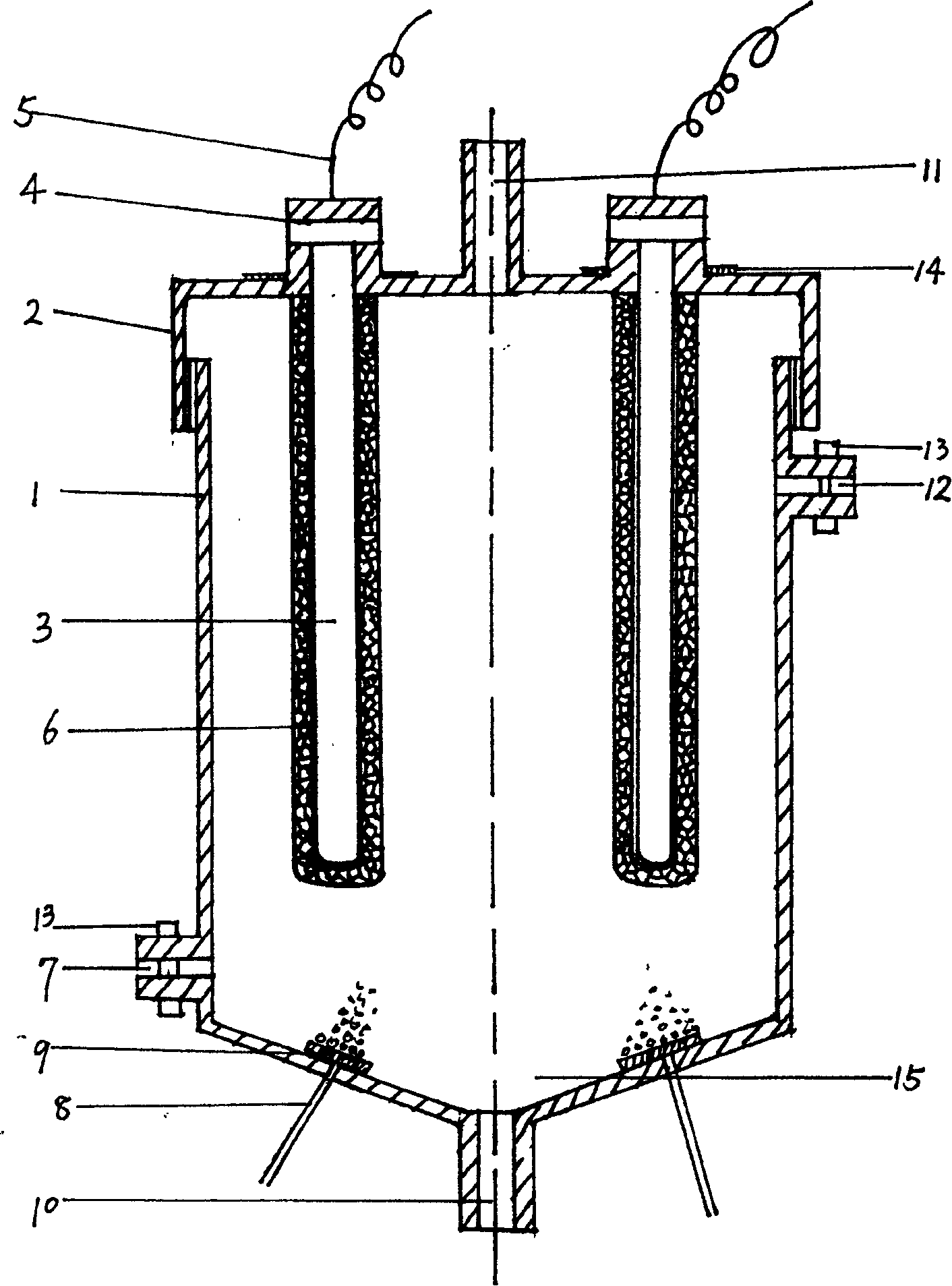
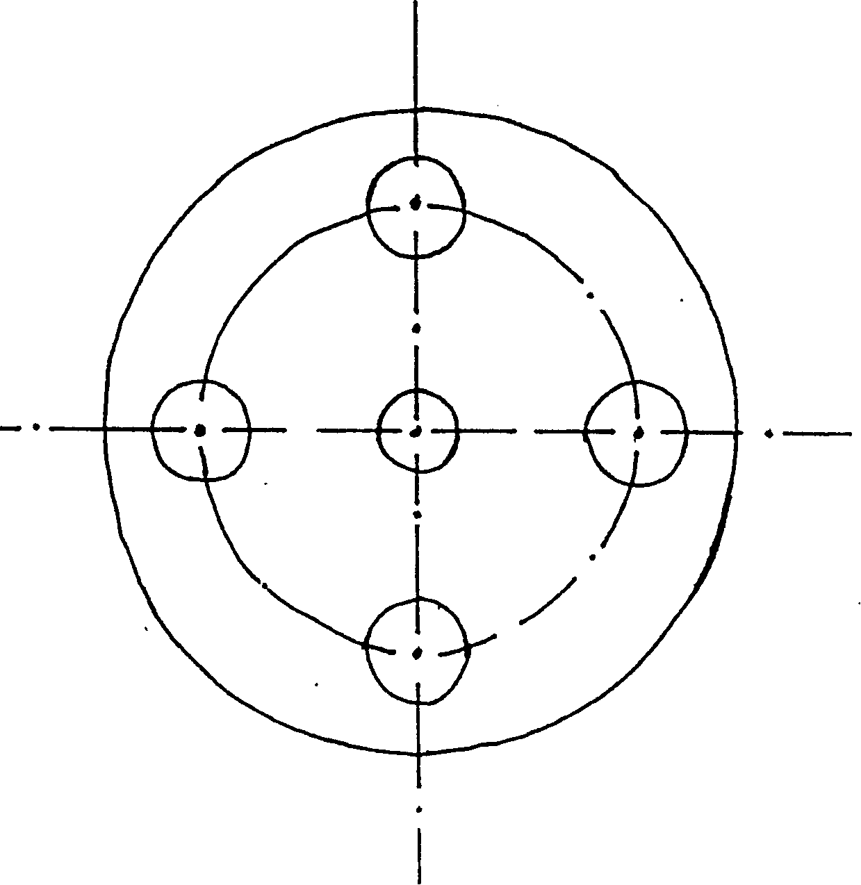
[0025] figure 1 , 2 The schematic structure of is a specific implementation structure of the photocatalytic reactor device of the present invention. The shell 1 of the reactor is made of stainless steel. The lower part of the side wall of the shell is provided with a water inlet 7, and the upper part is provided with a water outlet 12. Both the water inlet 7 and the water outlet 12 are equipped with a regulating valve 13. There are 4 Each photocatalytic assembly is composed of an ultraviolet lamp tube 3 and a photocatalyst package 6. The ultraviolet lamp tube is a high-pressure mercury lamp that can directly contact with water, and the lamp cap 4 of the light tube is fixed on a heat-resistant On the PVC plate 14, the PVC plate is fixed on the top cover 2 of the reactor, and the photocatalyst suite 6 is the carrier of the grid-shaped activated carbon fiber cylinder, and the photocatalyst TiO is attached on the surface of the activated carbon fiber and in the pores thereof. 2 ...

Embodiment 2

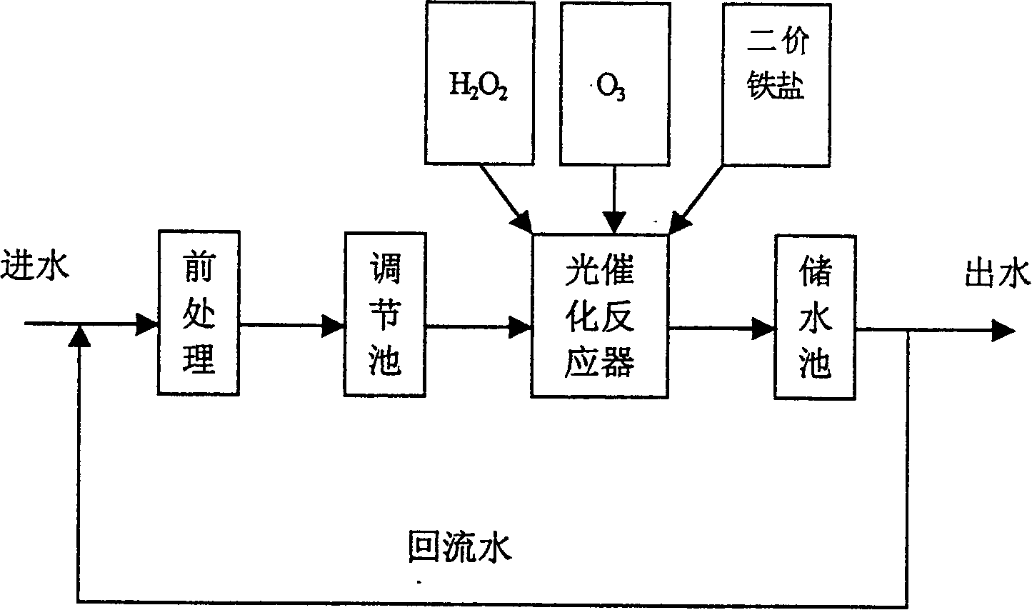
[0027] This example is the photocatalytic treatment of industrial wastewater from an organic additive factory. Its process is as image 3 shown. After the industrial wastewater is pre-treated by flocculation and sedimentation and then adjusted by the adjustment tank, the effluent COD is 2548.5mg / L, dinitrophenol is 128.7mg / L, aniline is 187.6 / L, and sulfide is 48.2mg / L. The waste water is passed into the photocatalytic reactor device, the flow rate is controlled to be 50L / hour, and 25mg / L of ozone is injected at the same time, and H 2 o 2 When the concentration reaches 0.6ml / L, add FeSO 4 When the concentration reaches 0.0045mol / L, the wastewater from the photocatalytic reactor device enters the storage tank for post-treatment, the wastewater reflux ratio is 100%, the hydraulic retention time is 6 hours, and the water quality entering the storage tank tends to be stable after 24 hours . The COD removal rate of the whole photocatalytic treatment process is 98.4%, the remov...

Embodiment 3

[0029] This example is a photocatalytic treatment of mixed wastewater from a dye factory. After the industrial wastewater is pre-treated by flocculation and sedimentation and then adjusted by the adjustment tank, the effluent COD is 3879.4mg / L, dinitrophenol is 312.1mg / L, aniline is 84.5 / L, chlorobenzene is 65.8mg / L, and sulfide is 21.5 mg / L. The waste water is treated by two-stage photocatalytic reactors, first passed into the first photocatalytic reactor device, the flow rate is controlled at 50L / hour, and 30mg / L of ozone is injected at the same time, and H 2 o 2 When the concentration reaches 0.9ml / L, add FeSO 4 When the concentration reaches 0.005mol / L, the wastewater from the photocatalytic reactor device enters the first storage tank for post-treatment, and the supernatant in it flows into the second photocatalytic reactor device, and the COD of the supernatant is 978.7 ~1235.1mg / L, flush into 20mg / L of ozone, add H 2 o 2 When the concentration reaches 0.3ml / L, add ...


PUM


Abstract

A technological scheme of treating organic waste water including pre-treatment, photocatalytic treatment and post-treatment, and during the photocatalytic treatment, a powerful reaction system is used and consists of TiO2 or modified TiO2 as catalyst, active carbon fiber net as catalyst carrier, and H2O2, O3 and two-valent ferrous salt as auxiliary oxidants and can result in multiple oxidation process including photocatalytic oxidation, photochemical oxidation, ferriin reagent oxidation, etc. The present invention also provides the specific design of a practical industrial photocatalytic reactor. The present invention is suitable for the effective degradation of organic matter in high-concentration difficult-to-degrade organic waste water.

Description

technical field [0001] The invention relates to a degradation treatment process for organic waste water and a treatment device thereof. Background technique [0002] In the organic wastewater produced by industries such as synthetic chemistry, polycyclic aromatic hydrocarbons (PAH) compounds, heterocyclic compounds, organic cyanides, synthetic detergents, polychlorinated biphenyls, synthetic pesticides, synthetic dyes, etc. are difficult to degrade and are toxic. Organic waste, this type of substance has a stable structure, and direct discharge is extremely harmful. At present, the treatment technologies for refractory organic wastewater mainly include adsorption method, membrane separation method, extraction method, photochemical method, ozone oxidation method, phenanthroline (Fenton) reagent method, biochar method, etc. The purpose of adsorption method, membrane separation method and extraction method is to separate the refractory organic substances, which will cause seco...

Claims


Application Information

Patent Timeline
Patent Type & Authority Patents(China)
IPC IPC(8): C02F1/30
Inventor 李芳柏黄志尧万洪富王卫红
Owner 广东顺德环境科学研究院有限公司
Why Eureka
Try Eureka