
Self-suction type X-ray generating device and application thereof

A generation device and X-ray technology, applied in the field of X-rays, can solve the problems of increasing the volume and design complexity of the X-ray tube, increasing the manufacturing cost of the X-ray tube, and affecting the imaging effect of the X-ray tube, so as to avoid occasional outgassing and eliminate mechanical damage. Vibration, to avoid the effect of falling powder

Active Publication Date: 2020-02-07
THE NAT CENT FOR NANOSCI & TECH NCNST OF CHINA
View PDF6 Cites 0 Cited by
  • Summary
  • Abstract
  • Description
  • Claims
  • Application Information

AI Technical Summary

Problems solved by technology

However, the above two methods have certain disadvantages: the getter has an adsorption effect on gas molecules with high chemical activity, but has no adsorption capacity for inert gases such as helium (He) and argon (Ar), and there are powder falling and occasional outgassing and other disadvantages; the vacuum exhaust device in the open structure increases the volume and design complexity of the ray tube, and is easy to introduce mechanical vibration, which affects the imaging effect of the ray tube and increases the manufacturing cost of the ray tube
[0005] From the above description, it can be seen that in terms of maintaining the vacuum inside the X-ray tube, no matter whether the getter or the vacuum exhaust device is used, there are certain disadvantages.
And in recent years, with the emergence of cold-cathode X-ray tubes, higher requirements have been put forward for its internal vacuum, which makes the vacuum maintenance of X-ray tubes face more challenges.

Method used


Image

  • Self-suction type X-ray generating device and application thereof
  • Self-suction type X-ray generating device and application thereof
  • Self-suction type X-ray generating device and application thereof

Examples


Embodiment 1

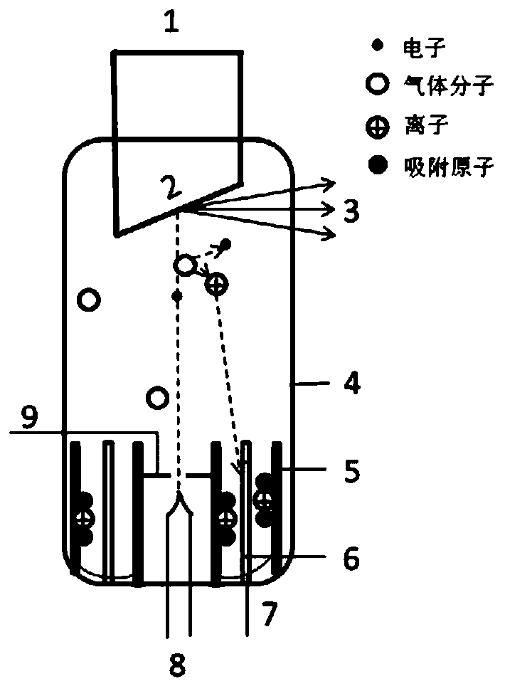
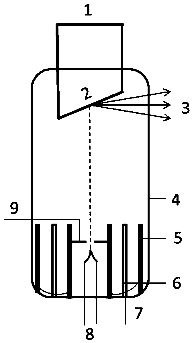
[0055] This embodiment provides a self-breathing sealed X-ray tube structure for hot cathodes, and its structural schematic diagram is as follows figure 2 As shown, it mainly includes: anode 1, target surface 2, X-ray window 3, insulating case 4, adsorption metal plate 5, sputtering metal plate 6, lead wire 7 shared by grid and adsorption metal plate, cathode 8, grid 9 .

[0056] Wherein, the cathode 8 is a filament, encapsulated in the insulating shell 4, and used for releasing electrons;

[0057] The anode 1 is packaged in the insulating case 4, the anode 1 includes a target body and a target surface 2, and the anode 1 releases X-rays by colliding with electrons released from the cathode 8;

[0058] The number of the adsorption metal plates 5 is four, the number of the sputtering metal plates 6 is two, and there are two groups of ion sputtering structures on both sides of the cathode 8, specifically, two groups of ion sputtering structures The sputtering structure is form...

Embodiment 2

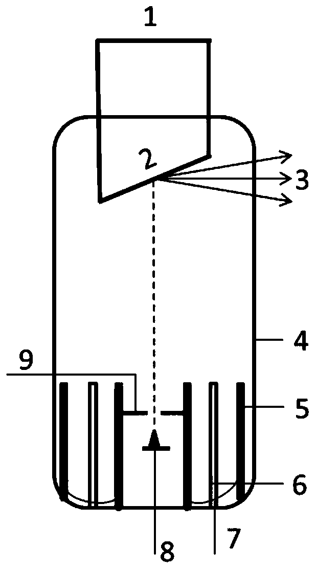
[0065] This embodiment provides a self-breathing sealed X-ray tube structure for a cold cathode, and its structural schematic diagram is as follows image 3 As shown, it mainly includes: anode 1, target surface 2, X-ray window 3, insulating case 4, adsorption metal plate 5, sputtering metal plate 6, lead wire 7 shared by grid and adsorption metal plate, cathode 8, grid 9 .

[0066] Wherein, the cathode 8 is a cold cathode, which is packaged in the insulating case 4 for releasing electrons;

[0067] The anode 1 is packaged in the insulating case 4, the anode 1 includes a target body and a target surface 2, and the anode 1 releases X-rays by colliding with electrons released from the cathode 8;

[0068] The number of the adsorption metal plates 5 is four, the number of the sputtering metal plates 6 is two, and there are two groups of ion sputtering structures on both sides of the cathode 8, specifically, two groups of ion sputtering structures The sputtering structure is forme...

Embodiment 3

[0075] This embodiment provides a micro-focus X-ray tube for self-adsorption type cold cathode transmission target, and its structural schematic diagram is as follows Figure 4 As shown, it mainly includes: anode 1, target surface 2, X-ray window 3, insulating shell 4, adsorption metal plate 5, sputtering metal plate 6, lead wire 7 shared by grid and adsorption metal plate, cold cathode and lead wire 8, Grid 9, focusing pole 10.

[0076] The anode described in this embodiment is a transmission anode target.

[0077] The structural difference between this embodiment and Embodiment 2 is that: the X-ray tube of this embodiment further includes two focusing electrodes 10 , and these two focusing electrodes 10 are located on the electron transmission path to converge the electron beams.

[0078] By adjusting different converging electrode structures and parameters, micro-focus spot electron beams (less than 100 microns) can be realized on the target surface, and the electron beams...


PUM


Abstract

The invention discloses a self-suction type X-ray generating device and application thereof. The device comprises an insulating shell, a cathode, an anode, a grid, at least one adsorption metal plateand at least one sputtering metal plate, the cathode is packaged in the insulating shell and is used for releasing electrons; the anode is packaged in the insulating shell, the anode comprises a target body and a target surface, and electrons released by the cathode collide with the target surface to release X-rays; the at least one adsorption metal plate and the at least one sputtering metal plate are arranged in parallel, each adsorption metal plate and the sputtering metal plate adjacent to the adsorption metal plate form one group of ion sputtering structures, there is at least one group of the ion sputtering structures, the at least one group of the ion sputtering structures are located at the at least one side of the cathode, and the plane directions of the at least one adsorption metal plate and the at least one sputtering metal plate are parallel to the electron release direction of the cathode; and the gate may be disposed on the at least one adsorption metal plate or the at least one sputtering metal plate or disposed separately. By introducing the ion sputtering structures, residual gas molecules in the X-ray tube are adsorbed while the X-ray tube emits, and a better vacuum degree is obtained.

Description

technical field [0001] The invention is used in the technical field of X-rays, and relates to a self-inhalation X-ray generating device and its application, which can effectively improve the vacuum degree of vacuum electronic devices. Background technique [0002] Since its discovery, X-rays have been widely used in medical imaging, industrial inspection, material analysis, security inspection and other fields, and play a huge role in daily life and industrial production. Although there are many ways to obtain X-rays, the most important form of application is to accelerate the electron beam bombardment of the anode target in a vacuum environment. In this process, the electron beam needs to fly a certain distance in vacuum, so as to realize the emission, focusing, acceleration, and other beam shape processing of the electron beam. Since the anode high voltage of the X-ray tube is generally between tens and hundreds of kilovolts, the electrical insulation between the anode an...

Claims


Application Information

Patent Timeline
Patent Type & Authority Applications(China)
IPC IPC(8): H01J35/24H01J35/06H01J35/08H01J35/02
CPCH01J35/24H01J35/06H01J35/08H01J35/02
Inventor 戴庆李振军李驰白冰陈科周圣涵
Owner THE NAT CENT FOR NANOSCI & TECH NCNST OF CHINA
Learn More